Difference between revisions of "Raspberry Pi camera extension kit"
| Line 3: | Line 3: | ||
== Overview == |
== Overview == |
||
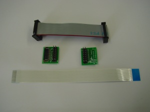
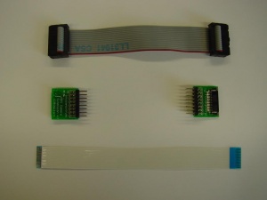
This kit allows you to expand the length of the Raspberry Pi camera by converting the standard FFC cable to a generic 2.54mm pin set. You could use the attached connectors to create a ribbon cable, let us create the ribbon cable, or use your own cable. Please note that the ribbon cable has an angled connector. The kit can be found in the shop [http://www.bitwizard.nl/ |
This kit allows you to expand the length of the Raspberry Pi camera by converting the standard FFC cable to a generic 2.54mm pin set. You could use the attached connectors to create a ribbon cable, let us create the ribbon cable, or use your own cable. Please note that the ribbon cable has an angled connector. The kit can be found in the shop [http://www.bitwizard.nl/shop/kits/rpi-camera-extension here] |
||
== Connecting == |
== Connecting == |
||
Latest revision as of 12:07, 2 November 2015
Overview
This kit allows you to expand the length of the Raspberry Pi camera by converting the standard FFC cable to a generic 2.54mm pin set. You could use the attached connectors to create a ribbon cable, let us create the ribbon cable, or use your own cable. Please note that the ribbon cable has an angled connector. The kit can be found in the shop here
Connecting
You can recognise this version by the way the connectors one the "camera board" converter are mounted on opposite sides of the PCB.
This is very straightforward:
- Turn off your Raspberry Pi
- Connect the opposite-side FPC cable (supplied with the kit) to the CSI connector of your Raspberry Pi, and the adapter board labeled "Raspberry Pi". The silver connectors on the FPC cable should face the HDMI connector on the raspberry pi side. On our adapter board the silver connectors on the FPC face AWAY from the PCB.
- Connect the opposite side FPC cable (supplied with the camera module) to the camera module, and the adapter board labeled "Camera board". Again on our adapter board the silver connectors on the FPC face AWAY from the PCB.
- Connect the IDC cable to both adapter boards. Make sure pin 1 of the cable lines up with de pin 1 markings on both adapter boards (please note: On the board marked with "Camera board", the pin 1 marking may be obstructed by the right-angle connector. On both boards the BitWizard logo is on the pin16 side of the board)
If you have trouble inserting the FPC into the connectors, please see: connecting FPCs.
Splitting cable
For more flexability, it is possible to split the cable into individual wires. Keep in mind that you have to keep the following wires fused together:
Pin 2&3
Pin 4&5
Pin 7&8
Pin 10&11
Pin 14&15

