Raspberry Relay
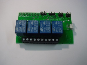
The Raspberry Relay board makes it possible to control 4 relays using your Raspberry Pi. It can be found in the shop here.
Overview
The Raspberry Relay board can be connected to a Raspberry Pi using the 26-pin GPIO connector. The relays can be controlled using the Raspberry Pi GPIO pins. Optionally, the Pi can be powered by the micro USB port on the Relay board. This way, the connectors for power, ethernet and USB are on one side. Please note that the polyfuse will be bypassed if the Pi is powered via the Relay board. The polyfuse prevents damage when a short-circuit occurs. If you power your Raspberry Pi with batteries, it is recommended to use the regular power connector, since a short-circuit could damage the battery. The positive side of bypassing the polyfuse is that the board is less sensitive to voltage fluctuations, since the polyfuse induces a 0.2V voltage drop.
Pinout
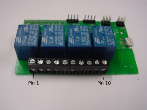
| Pin 1 | Pin 2 | Pin 3 | Pin 4 | Pin 5 | Pin 6 | Pin 7 | Pin 8 | Pin 9 | Pin 10 |
|---|---|---|---|---|---|---|---|---|---|
| Neutral | Relay 1 out | Neutral | Relay 2 out | Neutral | Relay 3 out | Neutral | Relay 4 out | Neutral | Hot |
If you want to switch mains, you should connect the 'Hot' wire to pin 10. In EU countries, this is usually the brown wire. The blue wire is the 'Neutral', and should be connected to pin 9. All other wires should be connected in the same way, so 'Neutral' to 'Neutral' and a 'Hot' wire to a relay output pin.
Usage
The module can be controlled with the GPIO pins on the Pi. Set a pin high, the relay will switch on and when the pin is low the relay will switch off. The pins are wired as follows:
| Relay no. | Pin number (by this scheme) | Pin name (Broadcom ref.) | Pin name (wiringPi) |
|---|---|---|---|
| 1 | 11 | GPIO17 | 0 |
| 2 | 12 | GPIO18 | 1 |
| 3 | 13 | GPIO21 (rev 1)/GPIO27 (rev 2) | 2 |
| 4 | 15 | GPIO22 | 3 |
Examples
Shell
- First, install WiringPi
- Set the GPIO modes:
gpio mode 0 out
gpio mode 1 out
gpio mode 2 out
gpio mode 3 out
- Enabling a relay:
gpio write X 1
where X is the relay number (0 to 3)
- Disabling a relay:
gpio write X 0
For more information about the gpio utility, see this page
Python
- Install the RPi.GPIO Python module:
sudo apt-get install python-rpi.gpio
- start the python interpreter
python
- or create a script
nano gpio.py
- The Python script should look like this:
#!/usr/bin/env python
#import the GPIO library
import RPi.GPIO as GPIO
#select the board mode pin numbering
GPIO.setmode(GPIO.BOARD)
#set the needed GPIO pins as output
GPIO.setup(11, GPIO.OUT) #relay 1
GPIO.setup(12, GPIO.OUT) #relay 2
GPIO.setup(13, GPIO.OUT) #relay 3
GPIO.setup(15, GPIO.OUT) #relay 4
#toggle the relays
GPIO.output(13,True) #Enable relay 3
GPIO.output(11,False) #Disable relay 1
- For more information on the RPi.GPIO module, see this page.
Datasheets
5A variant: Songle SRD-05VDC
10A variant: Omron G5LE-14


