Difference between revisions of "Raspberry Pi User Interface with 16 x 2 LCD with a console serial cable"
Jump to navigation
Jump to search
| Line 12: | Line 12: | ||
[[File:Rpi_ui_docu.png|none|thumb|500px|alt=The RPi_UI PCB|The RPi_UI PCB]] |
[[File:Rpi_ui_docu.png|none|thumb|500px|alt=The RPi_UI PCB|The RPi_UI PCB]] |
||
So to connect things up |
So to connect things up: |
||
Connect the black GROUND connector to the GND pin. The one nearest the I2C connector. |
* Connect the black GROUND connector to the GND pin. The one nearest the I2C connector. |
||
* Connect the green RXD cable to the next pin and |
|||
Connect the white TXD cable to the third pin. |
* Connect the white TXD cable to the third pin. |
||
You can leave the red VCC connector unconnected. |
You can leave the red VCC connector unconnected. |
||
Latest revision as of 13:34, 16 January 2013
Connecting the rpi_ui to a USB to TTL console cable.
The console cable manual show the following connection diagram:
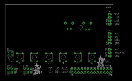
Our boards break out the uart pins on a 4-pin uart connector.
Here is a diagram (top view) of the rpi_ui. Even if it might show the 16x2, the 20x4 board has the pins in exactly the same order.
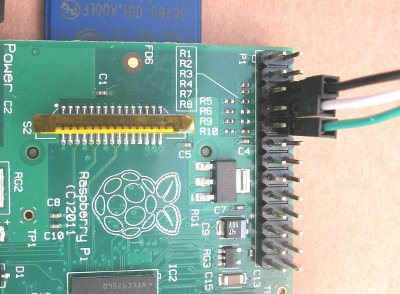
So to connect things up:
- Connect the black GROUND connector to the GND pin. The one nearest the I2C connector.
- Connect the green RXD cable to the next pin and
- Connect the white TXD cable to the third pin.
You can leave the red VCC connector unconnected.

