Difference between revisions of "Servo"
| Line 1: | Line 1: | ||
[[File:SPI_Servo.jpg|thumb|300px|alt=The SPI_Servo PCB|The |
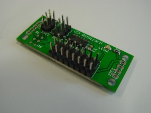
[[File:SPI_Servo.jpg|thumb|300px|alt=The SPI_Servo PCB|The Servo PCB (SPI version photographed)]] |
||
This is the documentation page for the SPI_servo |
This is the documentation page for the SPI_servo and I2C_SERVO boards. |
||
== Overview == |
== Overview == |
||
This module enables you to easily control upto 7 servomotors over an SPI interface, while needing minimal resources from your CPU. |
This module enables you to easily control upto 7 servomotors over an SPI or I2C interface, while needing minimal resources from your CPU. |
||
The PCB is equipped with two SPI connectors, so daisychaining multiple SPI modules is |
The PCB is equipped with two SPI or I2C connectors, so daisychaining multiple SPI or I2C modules is possible.<br> |
||
This allows you to control |
This allows you to control a chain of boards with only 4 data lines (MOSI, MISO, SS and SCK) for SPI or two lines (SDA, SCL) for I2C. This is not only pin-saving, but is is also possible do daisy-chain multiple modules (we will be releasing even more boards with other functions in the very near future)!<br> |
||
The board can be used with all microcontrollers, such as the Atmel AVR, Arduino/Freeduino boards, Microchip PIC, etcetera. |
The board can be used with all microcontrollers, such as the Atmel AVR, Arduino/Freeduino boards, Microchip PIC, Raspbery PI etcetera. <br> |
||
<br> |
<br> |
||
For small servos, the power supplied by the SPI connector is enough. For larger servos however, the voltage drop may be to high. We suggest conneting an auxillary 5V power source to the PCB, and |
For small servos, the power supplied by the SPI or I2C connector is enough. However current surges of up to a whole ampere are easily achieved even when two or three smaller servos need to move simultaneously. For larger servos however, the voltage drop may be to high. We suggest conneting an auxillary 5V power source to the PCB, and move the jumper. |
||
== External resources == |
== External resources == |
||
| Line 41: | Line 41: | ||
Solder jumper (on bottom layer): ICSP-Enable. CAUTION! Pin 1 and 2 are connected by a narrow PCB track. Cut this if you want to change this jumper setting.<br> |
Solder jumper (on bottom layer): ICSP-Enable. CAUTION! Pin 1 and 2 are connected by a narrow PCB track. Cut this if you want to change this jumper setting.<br> |
||
1-2: Default: Both SPI connectors connected in parallel.<br> |
1-2: Default: Both SPI connectors connected in parallel.<br> |
||
2-3: ICSP enabled; programming the MCU over the 6-pin connector marked SPI3 (near the edge of the board |
2-3: ICSP enabled; programming the MCU over the 6-pin connector. This connector may be marked SPI1 or SPI3 (near the edge of the board, furthest from the CPU.)<br> |
||
== Programming == |
== Programming == |
||
To control the servos, you need to send things over the |
To control the servos, you need to send things over the bus to the PCB. The [[spi_servo 1.0_protocol|protocol is explained here]]. |
||
== The software == |
== The software == |
||
Revision as of 16:20, 11 May 2012
This is the documentation page for the SPI_servo and I2C_SERVO boards.
Overview
This module enables you to easily control upto 7 servomotors over an SPI or I2C interface, while needing minimal resources from your CPU.
The PCB is equipped with two SPI or I2C connectors, so daisychaining multiple SPI or I2C modules is possible.
This allows you to control a chain of boards with only 4 data lines (MOSI, MISO, SS and SCK) for SPI or two lines (SDA, SCL) for I2C. This is not only pin-saving, but is is also possible do daisy-chain multiple modules (we will be releasing even more boards with other functions in the very near future)!
The board can be used with all microcontrollers, such as the Atmel AVR, Arduino/Freeduino boards, Microchip PIC, Raspbery PI etcetera.
For small servos, the power supplied by the SPI or I2C connector is enough. However current surges of up to a whole ampere are easily achieved even when two or three smaller servos need to move simultaneously. For larger servos however, the voltage drop may be to high. We suggest conneting an auxillary 5V power source to the PCB, and move the jumper.
External resources
Datasheets
The CPU: http://www.atmel.com/dyn/resources/prod_documents/doc8006.pdf
Additional software
Related projects
Pinout
The pinout is standard for servo-motors; Pin 1 is GND (near the edge of the board) Pin 2 is VCC (5V) Pin 3 is data
LEDs
The only LED is a power-LED.
Jumper settings
Solder jumper (on bottom layer): ICSP-Enable. CAUTION! Pin 1 and 2 are connected by a narrow PCB track. Cut this if you want to change this jumper setting.
1-2: Default: Both SPI connectors connected in parallel.
2-3: ICSP enabled; programming the MCU over the 6-pin connector. This connector may be marked SPI1 or SPI3 (near the edge of the board, furthest from the CPU.)
Programming
To control the servos, you need to send things over the bus to the PCB. The protocol is explained here.
The software
Default operation
Future hardware enhancements
Future software enhancements
Changelog
1.2
- Added jumper/power connector for (external) servo power.
1.0
- Initial public release
