Difference between revisions of "Power"
(Created page with "thumb|300px|alt=The power board|XXX need photo The DIO board (depicted: the SPI version) This is the documentation page for the SPI_POWER and I2C_POWERbo...") |
|||
| Line 11: | Line 11: | ||
None: the board comes fully assembled. |
None: the board comes fully assembled. |
||
== |
== Specifications == |
||
When you schedule a "wakeup" and then power down the slave, the module will enter a low-power mode. In this mode, it will consume about 2mA. The button is checked less often than when the module is fully away. A longer keypress may be required to activate the slave. |
|||
The current consumption will be about 10mA when the slave is active. The sleep mode cannot be activated because that would interfere with the communications protocols. |
|||
| ⚫ | |||
| ⚫ | |||
== Additional software == |
== Additional software == |
||
Latest revision as of 17:16, 2 June 2014
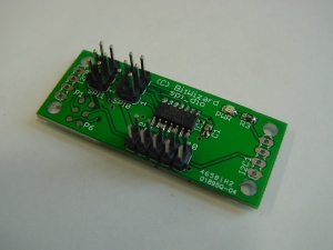
This is the documentation page for the SPI_POWER and I2C_POWERboards.
Overview
This board enables you to power your main CPU (e.g. a raspberry pi) from an USB powersupply. This board will then function as a powerswitch for your project. This is especially useful if you're running off a battery.
Assembly instructions
None: the board comes fully assembled.
Specifications
When you schedule a "wakeup" and then power down the slave, the module will enter a low-power mode. In this mode, it will consume about 2mA. The button is checked less often than when the module is fully away. A longer keypress may be required to activate the slave.
The current consumption will be about 10mA when the slave is active. The sleep mode cannot be activated because that would interfere with the communications protocols.
Datasheets
Additional software
Related projects
Pinout
For the SPI connector see: SPI_connector_pinout. For the I2C connector see: I2C_connector_pinout.
| pin | function |
|---|---|
| 1 | GND |
| 2 | SW |
By grounding "sw" you can toggle the powerstatus of the slave system.
LEDs
The only LED is a power indicator. To conserve power, the led is OFF when the slave is off.
jumper settings
See solder jumpers on how to change the solder jumper.
By changing the solder jumper SJ1, you can make the connector SPI1 (nearest the board edge) into an ICSP programming connector for the attiny44 on the board.
Protocol
For the intro to the SPI and I2C protocols read: SPI versus I2C protocols
The board specific protocol can be found here: POWER_protocol
You should also read the General_SPI_protocol notes.
The software
Default operation
Future hardware enhancements
Future software enhancements
Changelog
1.0
- Initial public release
