Difference between revisions of "Blog 21"
(→!BETA!) |
|||
| (One intermediate revision by the same user not shown) | |||
| Line 2: | Line 2: | ||
== !BETA! == |
== !BETA! == |
||
This is used for The project: |
|||
Hardware used on Raspberry Pi: |
|||
*[http://www.bitwizard.nl/shop/raspberry-pi-ui-16x2 RPi_UI board] | ([[User Interface]]) |
|||
*[http://www.bitwizard.nl/shop/expansion-boards/dio DIO] | ([[DIO]]) |
*[http://www.bitwizard.nl/shop/expansion-boards/dio DIO] | ([[DIO]]) |
||
*[http://www.bitwizard.nl/shop/cables-connectors/10-20cm-jumper-cables-m-f Jumper cables M-F] |
*[http://www.bitwizard.nl/shop/cables-connectors/10-20cm-jumper-cables-m-f Jumper cables M-F] |
||
*[http://www.bitwizard.nl/shop/cables-connectors/4-pin-cable-f-f 4 PIN I2C cable F-F] |
*[http://www.bitwizard.nl/shop/cables-connectors/4-pin-cable-f-f 4 PIN I2C cable F-F] |
||
*Analog |
*Analog meters |
||
Programmed with: |
Programmed with: |
||
*Bash |
|||
*Arduino |
|||
*[[Bw tool]] |
|||
*[https://github.com/PaulStoffregen/Time Time Library] |
|||
== Simple Example code == |
|||
In this code I will show how you can make the Analog meter pointer, be at 50% for ten seconds and being off for 10 seconds. |
|||
#define DIO 0x42 |
|||
#include <Wire.h> |
|||
void setup() |
|||
{ |
|||
Wire.begin(); // wake up I2C bus |
|||
Serial.begin(9600); |
|||
set_var(0x42, 0x30, 0x01); |
|||
set_var(0x42, 0x5f, 0x01); |
|||
} |
|||
byte get_var(byte address, byte reg) |
|||
{ |
|||
byte value; |
|||
Wire.beginTransmission(address); |
|||
Wire.write(reg); |
|||
Wire.endTransmission(); |
|||
delayMicroseconds (10); |
|||
Wire.requestFrom(DIO, 1); |
|||
value = Wire.read(); |
|||
return value; |
|||
} |
|||
void set_var(byte address, byte reg, byte value) |
|||
{ |
|||
Wire.beginTransmission(address); |
|||
delayMicroseconds (10); |
|||
Wire.write(reg); |
|||
delayMicroseconds (10); |
|||
Wire.write(value); |
|||
Wire.endTransmission(); |
|||
} |
|||
void loop() |
|||
{ |
|||
unsigned long DIOAddress; |
|||
char buf[32]; |
|||
set_var(0x42, 0x50, 0x80); |
|||
DIOAddress = get_var(0x50, 0xb); |
|||
sprintf (buf, "PWM80: A:%d \r\n", DIOAddress); |
|||
Serial.write (buf); |
|||
delay(10000); |
|||
set_var(0x42, 0x50, 0x00); |
|||
DIOAddress = get_var(0x50, 0xb); |
|||
sprintf (buf, "PWM0 : A:%d \r\n", DIOAddress); |
|||
Serial.write (buf); |
|||
delay(10000); |
|||
} |
|||
== Connecting the analog meters == |
== Connecting the analog meters == |
||
| Line 306: | Line 250: | ||
*[[DIO protocol]] |
*[[DIO protocol]] |
||
*[[User Interface]] |
*[[User Interface]] |
||
*[[Blog 22]] - The Arduino version of the above projects. |
|||
*[[Blog list]] |
*[[Blog list]] |
||
Latest revision as of 13:31, 23 December 2015
!BETA!
This is used for The project:
Hardware used on Raspberry Pi:
- RPi_UI board | (User Interface)
- DIO | (DIO)
- Jumper cables M-F
- 4 PIN I2C cable F-F
- Analog meters
Programmed with:
- Bash
- Bw tool
Connecting the analog meters
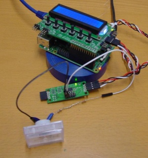
While making the analog meter clock, I encountered a problem. That I had one Alternating current voltage. So I had to make from the AC meter a DC meter.
For this I checked it out by putting the power resource after the diode.
When I connected the meter with a power resource, I directly found out it goes to fast to it's maximum. To change that it went so fast to it's maximum I added two resistors. The DIO should give 5 volt.
To check if the meter you have work on the DIO. Put the minus part of the meter on the GND(Pin 1), and the positive on the VCC(Pin 2). The pointer from the meter will directly go to the right. ( If he doesn't you have to change resistors, or look if everything is well connected )
To connect the meter with the DIO: I did in projects my positive cable on IO0, what is pin 3. ( The other cable has to go to GND Pin 1 ) On the wiki page of DIO you can see, which other pins are IO.
Change meter value through the command line
Recommended to use the DIO protocol.
I have in my example the analog meter connected with pin 3(IO0).
Pin 3 is IO0, so it will get the first value one. If you are going to change from pin you have to do all three commands, otherwise you have to do the first two commands only once.
To set pin 3 as output:
bw_tool -I -D /dev/i2c-1 -a 84 -W 30:01
To enable the PWM:
bw_tool -I -D /dev/i2c-1 -a 84 -W 5f:01
To let the pointer go to 50% of the analog meter:
bw_tool -I -D /dev/i2c-1 -a 84 -W 50:80
The value is in hexadecimals so that is why 80 is 50%.
If you are going to use a pin like pin 10(IO6). With the value 40 for register 30 and 5f. The reason it is 40 is, because the bits are in hexadecimals. So, 64 decimal bits gets calculated to 40 hexadecimals.
The reason why this is getting used, is because it is bit masked. With that you can add multiple pins in the command. So, if you you want pin 4(IO1) and pin 6(IO3) on:
IO1 + IO3 -> 02 + 08 = 0A
For the full Bit Mask list of values you have to go to the DIO protocol
Making the sticker
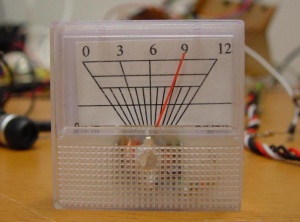
For making the sticker I first measured what the distance are from the the maximum and the minimum(0). I looked at the distance from horizontal and vertical. After that I made a picture of the meter. I used the program xfig to make the lines and put the image in the background. So, I know what to put where. After that I printed it out on a sticker paper, what I then put on my meter. It can be tricky work to do a sticker on a meter, so it is recommended to use tweezers. ( Or something else where you can hold it well with ) I used my fingers and that had the problem that my picture was not precisely placed.
DIO Analog meter - Clock
With this script, I made it possible to show how late it is on the analog meter. For now I only have one analog meter that works, so I will only show how late it's in hours. The script is pretty easy to understand, but I will still give some parts explanation.
This is the onexit script, What it does is when the script crashes or this function get named by the script. I will do the given commands and then exit the running script. So, in my case it turns the PWM back to zero on pin 3 (IO0), which makes the pointer go back to the left. It after that clears the screen. If you use a different Pin and don't know which one to use you have to look at the DIO Protocol page.
trap onexit 1 2 3 15 ERR

  function onexit() {
    $DIO -W 50:00 #Turns PWM back to zero
    $UI -W 10:00  #Clears screen
   exit
  }
This looks at what hour it's and puts it in the directory name Hour.
Hour=`date +%H`
What gets printed on the display.
$UI -t "Clock=" $Hour
The if statement looks at which hour there is given and looks if it is greater than the given value in $MAX. If it is 12 o’clock or later it will subtract 12 of it. So, for example 18 will become 6.
  if [ "$Hour" -gt "$MAX" ]; then
  Hour=$(( $Hour - $MAX ))
  fi
In the Array stands the amount of steps with the value it should give in hexadecimals.
  array=(   00 17 2E 45 5C 73 8A A1 B8 CF E6 FF )
  # Element 0  1  2  3  4  5  6  7  8  9  10 11
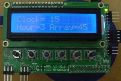
On the second row of the LCD display the value will be printed of the new hour ( if it is above 12 o'clock value ) and the hexadecimal value in the array.
  $UI -W 11:20
  $UI -t "Hour=$Hour Array="${array[$Hour]}
The full script:
#!/bin/bash

DIO="bw_tool -I -D /dev/i2c-1 -a 84"
UI="bw_tool -I -D /dev/i2c-1 -a 94"
MAX="12"

trap onexit 1 2 3 15 ERR

  function onexit() {
    $DIO -W 50:00 #Turns PWM back to zero
    $UI -W 10:00  #Clears screen
   exit
  }

while true; do
  Hour=`date +%H`
  #  Hour=$((Hour + 6)) #I made this at 12:00, so I added 6 so I can see if the meter works

  $UI -W 10:00
  $UI -t "Clock=" $Hour

  if [ "$Hour" -gt "$MAX" ]; then
  Hour=$(( $Hour - $MAX ))
  fi

  array=(   00 17 2E 45 5C 73 8A A1 B8 CF E6 FD )
  # Element 0  1  2  3  4  5  6  7  8  9  10 11

  $UI -W 11:20
  $UI -t "Hour=$Hour Array="${array[$Hour]}

  $DIO -W 50:${array[$Hour]}

  sleep 5
done
DIO Analog meter - Adjustable Timer
In this script I made an adjustable timer. That will let the meter go form the right to left and after that the raspberry pi will play a song.
The time of how long the progress has to take can be given after the script name. So, if you want the timer to take 30 seconds, it should look like this:
./"Scriptname" 30
The explanation of the script: Here it will give the amount of seconds the date program knows and give it to the variable Start. The variable Seconds will get the value put after the script name (as in the example above with the value 30 ) ( You can also change the Seconds value "$1" with the amount of seconds you want. ) The end variable counts the seconds and start variable together. I use this later in the script, so that it then knows when it reached it's maximum value.
Start=`date +%s`
Seconds="$1"
End=$(($Seconds + $Start))
The now variable gets in the while true list, and is used to read every time to look at which second it is now. In progress the end(where the time ends) and now get counted of each other. The PWM value gets calculated. What gives the percentage of 255 is used.
Now=`date +%s`
Progress=$(($End - $Now))
PWMValue=$(($Progress * $MAX / $Seconds))
Here is gives the hexadecimal output of the PWMValue. (So for example, the maximum value 255 would be FF.)
PWMValueHex=`(echo obase=16; echo $PWMValue ) | bc`
Here the the result gets send to the DIO and to the user interface. What makes that the analog meter is going to move and that on the display is visible what hexadecimal value it is.
$DIO -W 50:$PWMValueHex

$UI -W 11:20
$UI -t "Hex Value: " $PWMValueHex
In the onexit it looks if the now value has gotten equal of higher then the given end value, where it should have stopped. When the end value is getting reached or passed the onexit function is going to run.
if [ "$Now" -ge "$End" ]; then
  onexit
fi

sleep 1
The full script:
#!/bin/bash

DIO="bw_tool -I -D /dev/i2c-1 -a 84"
UI="bw_tool -I -D /dev/i2c-1 -a 94"
MAX="255"

Start=`date +%s`
Seconds="$1"
End=$(($Seconds + $Start))

trap onexit 1 2 3 15 ERR

function onexit() {
  $DIO -W 50:00 #Turns PWM back to zero
  $UI -W 10:00  #Clears screen
  #mplayer Song.mp3
 exit
}

while true; do
  Now=`date +%s`
  Progress=$(($End - $Now))
  PWMValue=$(($Progress * $MAX / $Seconds))

  PWMValueHex=`(echo obase=16; echo $PWMValue ) | bc`

  $DIO -W 50:$PWMValueHex

  $UI -W 11:20
  $UI -t "Hex Value: " $PWMValueHex

  if [ "$Now" -ge "$End" ]; then
    onexit
  fi

  sleep 1

done
onexit
Useful links
- DIO
- DIO protocol
- User Interface
- Blog 22 - The Arduino version of the above projects.
- Blog list


