Difference between revisions of "FT311D"
Jump to navigation
Jump to search
| (5 intermediate revisions by 2 users not shown) | |||
| Line 1: | Line 1: | ||
[[File:FT311D.jpg|thumb|300px]] |
[[File:FT311D.jpg|thumb|300px]] |
||
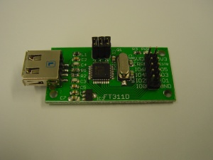
This is the documentation page for the FT311D breakout board. |
This is the documentation page for the FT311D breakout board. The can be bought in the [http://www.bitwizard.nl/shop/breakout-boards/ft331d-breakout-board BitWizard shop]. |
||
== |
== Overview == |
||
The FT311D breakout board has an USB connector, one 12-pin IO connector. The brains of the PCB, of course, is an FT311D chip. |
The FT311D breakout board has an USB connector, one 12-pin IO connector. The brains of the PCB, of course, is an FT311D chip. |
||
| Line 11: | Line 11: | ||
* [http://www.ftdichip.com/Support/Documents/DataSheets/ICs/DS_FT311D.pdf Datasheet] |
* [http://www.ftdichip.com/Support/Documents/DataSheets/ICs/DS_FT311D.pdf Datasheet] |
||
* [http://www.ftdichip.com/Products/ICs/FT311D.html FTDI product page] |
* [http://www.ftdichip.com/Products/ICs/FT311D.html FTDI product page] |
||
* [http://www.ftdichip.com/Support/Documents/AppNotes/AN_212%20User%20Guide%20for%20FT311%20Configuration%20Utility.pdf FTDI appnote. Helps with development.] |
|||
== |
== Using the board == |
||
The board can not be powered from your mobile phone, you will need to supply 5V on the 5V header pin. This will also charge your phone. |
|||
This board is compatible with AOA (Android Open Accessory), and for example the PodMode app. |
|||
== Pinout == |
|||
The 12-pin connector is connected as follows: |
The 12-pin connector is connected as follows: |
||
| Line 33: | Line 40: | ||
* The jumpers are, from left to right, for CNFG2, CNFG1, and CNFG0. Placing a jumper connects the config pin to GND, removing it leaves the pin open. Please see the datasheet for the correct jumper settings. |
* The jumpers are, from left to right, for CNFG2, CNFG1, and CNFG0. Placing a jumper connects the config pin to GND, removing it leaves the pin open. Please see the datasheet for the correct jumper settings. |
||
== |
== Future hardware enhancements == |
||
* jumper to be able to disconnect the 5V header pin from the 5V USB pin |
|||
== Changelog == |
== Changelog == |
||
Latest revision as of 13:32, 21 July 2016
This is the documentation page for the FT311D breakout board. The can be bought in the BitWizard shop.
Overview
The FT311D breakout board has an USB connector, one 12-pin IO connector. The brains of the PCB, of course, is an FT311D chip.
External resources
Using the board
The board can not be powered from your mobile phone, you will need to supply 5V on the 5V header pin. This will also charge your phone.
This board is compatible with AOA (Android Open Accessory), and for example the PodMode app.
Pinout
The 12-pin connector is connected as follows:
| 5V | 3V3 |
| USB ERROR#(jumpered) | TEST0 |
| IOBUS6 | IOBUS5 |
| IOBUS4 | IOBUS3 |
| IOBUS2 | IOBUS1 |
| IOBUS0 | GND |
LEDS
- The only LED is a power LED
Jumper settings
- The jumpers are, from left to right, for CNFG2, CNFG1, and CNFG0. Placing a jumper connects the config pin to GND, removing it leaves the pin open. Please see the datasheet for the correct jumper settings.
Future hardware enhancements
- jumper to be able to disconnect the 5V header pin from the 5V USB pin
Changelog
1.1
- Initial public release
