Difference between revisions of "LCD"
| Line 43: | Line 43: | ||
For use with the raspberry pi use the bw_rpi_tools package (and then only the bw_tool program) from github: [[https://github.com/rewolff/bw_rpi_tools]] |
|||
For use with a raspberry pi there are a few options. For the I2C version, you can get http://www.bitwizard.nl/software/bw_rpi_tools-20120616.tgz . The GPIO directory in that archive contains some programs to communicate with the LCD with a userspace driver. There is also a kernel-space driver for the I2C module, but I haven't looked at accessing that from userspace yet. (the kernel-space driver will allow other kernel drivers, for example for a temperature sensor, to access the I2C bus). |
|||
For SPI on the raspberry pi, the same gpio directory contains "send_spi". It will allow you to send stuff to the SPI display. |
|||
For SPI there is also a beta kernel driver. That is what the other directory bw_spi is for. |
|||
=== Related projects === |
=== Related projects === |
||
Revision as of 10:00, 11 February 2013
This is the documentation page for the SPI_LCD and I2C_LCD boards.
Overview
Assembly instructions
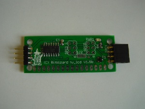
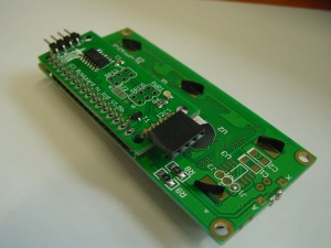
The board comes fully assembled, as depicted in the picture on the top right of this page..
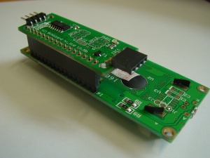
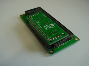
We assemble the ones with LCD with just a pin header between the board and the LCD, so you could do the same. Make sure you put the LCD in correctly. I'm not sure everything survives the wrong polarity.
Possible Configurations
For the SPI version the second SPI port can be used as an ICSP connector. You need to toggle the solder jumper for this. The I2C or SPI bus cannot be left connected during programming.
The contrast setting depends strongly on the voltage of the power line. We test the boards with our powersupply and deliver them with a contrast setting that works for us. However if your powersupply has a higher or lower voltage, the proper contrast setting might be different.
External resources
Datasheets
The fet: http://www.irf.com/product-info/datasheets/data/irlml2244pbf.pdf
The CPU: http://www.atmel.com/dyn/resources/prod_documents/doc8006.pdf
Additional software
For the I2c version there is a demo project for arduino at http://www.bitwizard.nl/software/ar_i2c_lcd_demo.pde
For the SPI version there is a demo project for arduino at http://www.bitwizard.nl/software/ardemo_lcd.pde
For use with the raspberry pi use the bw_rpi_tools package (and then only the bw_tool program) from github: [[1]]
Related projects
Pinout
For the SPI connector see: SPI_connector_pinout.
For the I2C connector see: I2C_connector_pinout.
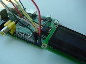
To connect the I2C board to a raspberry pi without a converter board ("rpi_serial"), you can use 4 separate wires. This is shown here:
LEDs
The only LED is a power indicator.
Jumper settings
There are two solder jumpers. The one between the two 6-pin SPI connectors controls the function of the SPI connector furthest from the CPU.
In the default configuration the second SPI connector is a daisy-chain connector for the SPI bus.
In the other configuration, the second SPI connector is the ICSP connector.
There is a 10 mil (very small) PCB trace in the solder jumper in the default configuration. You'll have to cut this trace to move the solderjumper to the other position. If you later decide you want the other configuration again, some solder-wick can be used to remove the solder from one position and then it can be added to the other position.
Programming
For the intro to the SPI and I2C protocols read: SPI versus I2C protocols
The board specific protocol can be found here: lcd protocol 1.6 (both I2C and SPI). For reference: here are older versions of the document: spi_lcd 1.3_protocol spi_lcd_1.2_protocol i2c_lcd_protocol
You should also read the General_SPI_protocol notes.
For arduino, a sample PDE is available, called ardemo_lcd.pde, also at BitWizard software download directory .
This is a demo to send things using SPI to the lcd board. The SPI routines there are applicable for LCD boards as well.
troubleshooting
If your display stays blank while turning on your system, this might be an indication of that the power supply is rising too slowly. In that case, the processor on your spi_lcd or i2c_lcd board is booting before the controller on the LCD sub-assembly has enough power to work. In that case, you need to send a dummy byte to the 0x14 port. This will reinitialise the LCD.
The software
If you are going to connect your I2C_LCD or SPI_LCD to a raspbery pi, read: getting started with rpi_serial and BitWizard expansion boards
Future hardware enhancements
hardware potentiometer for the contrast. (option).
Future software enhancements
- Lock the address. (require a sequence of commands to change the address).
Changelog
1.2
- Initial public release
