Difference between revisions of "Blog 23"
| Line 41: | Line 41: | ||
=== Arduino === |
=== Arduino === |
||
The above explanation should |
The above explanation should look this on arduino: |
||
void setup() |
void setup() |
||
{ |
{ |
||
Latest revision as of 12:48, 29 December 2015
Working with multiple analog meters
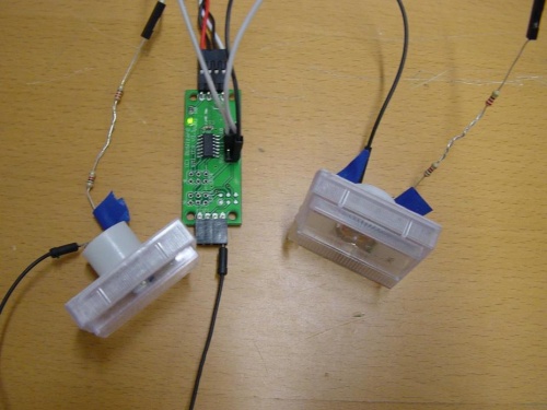
I got my second analog meter too late, thanks to that my previous clocks/timers only have one analog meter in them. But now I got my second analog meter I still want to explain how to get two analog meters to work on one DIO. Note my explanations are made for the I2C.
Connecting the second analog meter
The second analog meter I put on pin 4. The DIO has at the connector pins only one ground. That is why I instead of using a splitter, I just used the I2C connector as ground.
The Code: You probably read this before. But when you want to let the pins work you have to follow three steps. The first two steps are that you have to enable the PWM and defining which pin as output. With register 30 you define which pin is an output. With register 5f you define which pin has to have PWM enabled. In my example I have the meter connected with pin 3(IO0) + 4(IO1). The registers work with bitmasking. So, that means that in my example I have to calculate: Pin 3 + Pin 4 => 01 + 02 = 03. With that I have to give the value 03. Now you can change the PWM value of the two pins. You can this by using register 50-56( From the first pin to the last pin ). I want to get the first pin have maximum PWM and the second 50%. The first pin should be register 50 and the value FF. ( It works in two hexadecimals ) The second pin should be register 51 with the value 80.
More about what values are given to which pin you can read in the: DIO protocol
Raspberry Pi
The above explanation should look like this in bash code:
bw_tool -I -D /dev/i2c-1 -a 84 -W 30:03
bw_tool -I -D /dev/i2c-1 -a 84 -W 5f:03
bw_tool -I -D /dev/i2c-1 -a 84 -W 50:FF
bw_tool -I -D /dev/i2c-1 -a 84 -W 50:80
Arduino
The above explanation should look this on arduino:
void setup()
{
  Wire.begin(); // wake up I2C bus
  Serial.begin(9600);
  set_var(0x42, 0x30, 0x03);
  set_var(0x42, 0x5f, 0x03);
  set_var(0x42, 0x50, 0xFF);
  set_var(0x42, 0x51, 0x80);
}
Useful links
- DIO
- DIO protocol
- Blog 21 - For the original Raspberry Pi version of the clock and timer.
- Blog 22 - For the original Arduino version of the clock and timer.
