Difference between revisions of "Raspberry Relay"
Jump to navigation
Jump to search
(→Usage) |
|||
| Line 18: | Line 18: | ||
| 4 || 15 || GPIO22 || 3 |
| 4 || 15 || GPIO22 || 3 |
||
|} |
|} |
||
== Datasheets == |
|||
5A variant: [http://www.parallax.com/sites/default/files/downloads/27115-Single-Relay-Board-Datasheet.pdf Songle SRD] |
|||
Revision as of 14:11, 25 August 2014
Overview
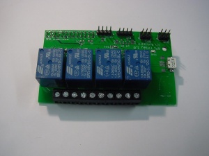
The Raspberry Relay board can be connected to a Raspberry Pi using the 26-pin GPIO connector. The relays can be controlled using the Raspberry Pi GPIO pins. Optionally, the Pi can be powered by the micro USB port on the Relay board. This way, the connectors for power, ethernet and USB are on one side. Please note that the polyfuse will be bypassed if the Pi is powered via the Relay board. The polyfuse prevents damage when a short-circuit occurs.
Usage
The module can be controlled with the GPIO pins on the Pi. Set a pin high, the relay will switch on and when the pin is low the relay will switch off. The pins are wired as follows:
| Relay no. | Pin number | Pin name (Broadcom ref.) | Pin name (wiringPi) |
|---|---|---|---|
| 1 | 11 | GPIO17 | 0 |
| 2 | 12 | GPIO18 | 1 |
| 3 | 13 | GPIO21 (rev 1)/GPIO27 (rev 2) | 2 |
| 4 | 15 | GPIO22 | 3 |
Datasheets
5A variant: Songle SRD
