Difference between revisions of "FT245RL V1.5"
Jump to navigation
Jump to search
(Created page with "This is the documentation page for the FT245RL breakout board. == overview == The FT245RL breakout board has an USB connector, one 16-pin IO connector. The brains of the PC...") |
|||
| Line 1: | Line 1: | ||
[[File:FT245RL.jpg|thumb|300px]] |
|||
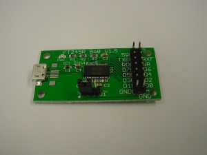
This is the documentation page for the FT245RL breakout board. |
This is the documentation page for the FT245RL breakout board. |
||
Revision as of 17:31, 16 September 2014
This is the documentation page for the FT245RL breakout board.
overview
The FT245RL breakout board has an USB connector, one 16-pin IO connector. The brains of the PCB, of course, is an FT245RL chip.
External resources
pinout
The 16-pin connector is connected as follows:
| 5V | 3V3 |
| TXE# | RXF# |
| RD# | WR |
| D7 | D5 |
| D5 | D4 |
| D3 | D2 |
| D1 | D0 |
| GND | GND |
LEDS
- The only LED is a power LED
Jumper settings
The only jumper is for selecting the I/O voltage. Place the jumper on the left side for 3V3, or on the right side for 5V.
future hardware enhancements
Changelog
1.1
- Initial public release
