Difference between revisions of "FT311D"
Jump to navigation
Jump to search
(Created page with "This is the documentation page for the FT311D breakout board. == overview == The FT311D breakout board has an USB connector, one 12-pin IO connector. The brains of the PCB,...") |
|||
| Line 1: | Line 1: | ||
[[File:FT311D.jpg|thumb|300px]] |
|||
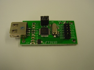
This is the documentation page for the FT311D breakout board. |
This is the documentation page for the FT311D breakout board. |
||
Revision as of 17:31, 16 September 2014
This is the documentation page for the FT311D breakout board.
overview
The FT311D breakout board has an USB connector, one 12-pin IO connector. The brains of the PCB, of course, is an FT311D chip.
External resources
pinout
The 12-pin connector is connected as follows:
| 5V | 3V3 |
| USB ERROR#(jumpered) | TEST0 |
| IOBUS6 | IOBUS5 |
| IOBUS4 | IOBUS3 |
| IOBUS2 | IOBUS1 |
| IOBUS0 | GND |
LEDS
- The only LED is a power LED
Jumper settings
- The jumpers are, from left to right, for CNFG2, CNFG1, and CNFG0. Placing a jumper connects the config pin to GND, removing it leaves the pin open. Please see the datasheet for the correct jumper settings.
future hardware enhancements
Changelog
1.1
- Initial public release
