Blog 17
2 Wheel controlled car
I made this on the Raspbery Pi for the stepper motor and for 'electric wheels'.
Stepper motor version
Hardware I used on my Raspberry Pi:
- One RPi_UI board | (User Interface)
- Two 7FETs | (7FETs)
- Two Jumper cables M-F
- Two IDC cable 6 pin
- Two 28BYJ-48 Stepper Motor
Programming:
- Bash
The full car just went to be a carton box, with everything attached to it with tieraps.
3D printed wheels code
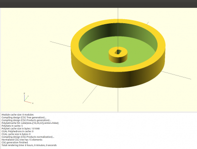
I made the wheels in OpenSCAD and let them be printed out on a 3d printer. The diameter of the wheel is 60mm and is 12mm high. The hole in the middle was made to put in the 28BYJ-48 Stepper Motor. The OpenSCAD code:
$fs=0.2; $fa=2;

module stepperas(d=5, l=25, t=3)
{
  difference()
  {
    cylinder (r=d/2 , h=l);
translate ([t/2, -5, -1])   cube([10, 20, l+2]);
translate ([-t/2-10, -5, -1])  cube([10, 20, l+2]);

  }
}

difference()
{
  union () {
    difference () {
      cylinder (r=60/2 ,h=12);
      translate ([0, 0, 1.5])
        cylinder (r=50/2, h=20);
    }
    cylinder (r=6,h=6);
  }

  translate ([0, 0, -1])
    stepperas(5.2, 20, 3.2);
}
The result of the OpenSCAD code (Press F5 to see it in OpenSCAD):
Code
Here is a list of the commands one of each other, that you could send to the stepper motor.
#!/bin/bash

#Address=spi0   address2=spi1
Address="bw_tool -s 50000 -a 88"
Address2="bw_tool -S -D /dev/spidev0.1 -a 88"

#800 is rotating a full circle
Rot=800
Target=`$Address -R 41:i`

Speed1=0x200
Speed2=0x100
#Speed3=0x50
#Speed4=0xff

#Turn left
$Address -W 43:$Speed1:b
$Address -W 42:$Rot:i
$Address2 -W 43:$Speed2:b
$Address2 -W 42:$Rot:i
sleep 10

#Turn Right
$Address -W 43:$Speed2:b
$Address -W 42:$Rot:i
$Address2 -W 43:$Speed1:b
$Address2 -W 42:$Rot:i
sleep 10

#Go Forwards
$Address -W 43:$Speed2:b
$Address -W 42:-$Rot:i
$Address2 -W 43:$Speed2:b
$Address2 -W 42:$Rot:i
sleep 10

#Go Backwards
$Address -W 43:$Speed2:b
$Address -W 42:$Rot:i
$Address2 -W 43:$Speed2:b
$Address2 -W 42:-$Rot:i
sleep 10

#Spin right
$Address -W 43:$Speed2:b
$Address -W 42:$Rot:i
$Address2 -W 43:$Speed1:b
$Address2 -W 42:-$Rot:i
sleep 10

#Spin left
$Address -W 43:$Speed2:b
$Address -W 42:-$Rot:i
$Address2 -W 43:$Speed1:b
$Address2 -W 42:$Rot:i
'Electric wheels' version
Hardware I used on my Raspberry Pi:
- One RPi_UI board | (User Interface)
- One Motor | (Motor)
- One Cable, 4 Pin (I2C), F-F
- Two single Jumper cables M-M
- Two electric wheels
- Soft cables ( To connect to the motor and the wheels )
- One dongle
To put the wheels on the board: I just made some holes and put some tieraps around the board to hold the electric wheels.
Cable connection:
| pin | function | cable | |
|---|---|---|---|
| 1 | Output B1 | Black (Connected with right wheel down) | |
| 2 | Output B2 | Red (Connected with right wheel up) | |
| 3 | Output A1 | Black (Connected with left wheel down) | |
| 4 | Output A2 | Red (Connected with left wheel top) | |
| 5 | GND | White Jumper Cable M-M (Connected with the ground from the battery) | |
| 6 | Vin | Red Jumper Cable M-M (Connected with the power from the battery) |
The cables and jumper cables can of course be different colors, but I told the color for the images. The reason I used the jumper cable M-M is because it is easier to put in the battery.
Programming:
- Bash
Script:
#!/bin/bash

#Wheel A left forward
#Wheel B Right forward

# X is forwards - Y is backwards
#Wheels at front
#20  A backwards
#21  A forwards
#22  A stop
#30  B backwards
#31  B forwards
#32  B stop

Address="bw_tool -I -D /dev/i2c-1 -a 90"
Speed="80"
Speed2="40"

while true; do
  BUTTON=`bw_tool -I -D /dev/i2c-1 -a 94 -R 30:b`

  if [ $BUTTON  = "20" ]; then
  #Car going forwards
  $Address -W 21:$Speed:b
  $Address -W 31:$Speed:b
  fi

  if [ $BUTTON  = "10" ]; then
  #Car going backwards
  $Address -W 20:$Speed:b
  $Address -W 30:$Speed:b

  if [ $BUTTON  = "08" ]; then
  #Car going left
  $Address -W 21:$Speed2:b
  $Address -W 31:$Speed:b
  fi

  if [ $BUTTON  = "04" ]; then
  #Car going right
  $Address -W 21:$Speed:b
  $Address -W 31:$Speed2:b
  fi

  if [ $BUTTON  = "02" ]; then
  #Car Stop
  $Address -W 22:$Speed:b
  $Address -W 32:$Speed:b
  fi

  if [ $BUTTON  = "01" ]; then
  exit
  fi

  sleep 1
done
Other movements:
#Spinning right
bw_tool -I -D /dev/i2c-1 -a 90 -W 20:80:b
bw_tool -I -D /dev/i2c-1 -a 90 -W 31:80:b

#Spinning left
bw_tool -I -D /dev/i2c-1 -a 90 -W 21:80:b
bw_tool -I -D /dev/i2c-1 -a 90 -W 30:80:b
I think the code pretty much explains itself with the extra info I have given it. I used the push buttons as example of how it could be used. All the protocols can been found in Motor protocol.
Useful links
- Working with a 7FETs Stepper motors Blog 15
- Working with multiple 7FETs Stepper motors Blog 16
- Blog list ( Overview of all my posts )
- Motor protocol
- OpenSCAD documentation
