Dio breakout
The printable version is no longer supported and may have rendering errors. Please update your browser bookmarks and please use the default browser print function instead.
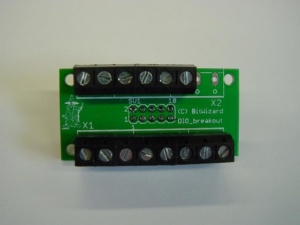
This is the documentation page for the DIO_breakout .
Overview
This board enables use screw terminals to connect wires to your SPI_DIO or I2C_DIO board.
Assembly instructions
None: the board comes fully assembled.
Additional software
Related projects
Pinout
The connector at the bottom of the board is laid out as follows:
| pin | function |
|---|---|
| 1 | GND |
| 2 | IO0 |
| 3 | IO1 |
| 4 | IO2 |
| 5 | IO3 |
| 6 | IO4 |
| 7 | IO5 |
| 8 | IO6 |
the power-connector at the top of the board is laid out as follows:
| pin | function |
|---|---|
| 1 | GND |
| 2 | VCC |
| 3 | GND |
| 4 | VCC |
| 5 | GND |
| 6 | VCC |
| 7 | GND |
| 8 | VCC |
The dataconnector in the middle of the board is compatible with the DIO board:
| pin | function |
|---|---|
| 1 | GND |
| 2 | VCC |
| 3 | IO0 |
| 4 | IO1 |
| 5 | IO2 |
| 6 | IO3 |
| 7 | d.n.c. |
| 8 | IO4 |
| 9 | IO5 |
| 10 | IO6 |
jumper settings
There are no jumpers.
Future hardware enhancements
Future software enhancements
Changelog
1.0
- Initial public release
