Blog 14
The BigRelay board
In this post I will show my scripts for Raspberry Pi and Arduino, where I will let every relay one after another turn on and off. This can be a handy script, if you want to give a quick look if all the relays work.
Hardware I used for the Raspberry Pi:
- RPi_UI board (User Interface)
- BigRelay board (Relay)
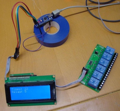
Hardware I used for the Arduino:
Raspberry Pi version
The script of the bash program:
#!/bin/bash

OnTime=1
OffTime=0

bigrelay="bw_tool -s 50000 -a 9c"

trap onexit 1 2 3 15 ERR

function onexit() {
  $bigrelay -W 10:0:b
  exit
}

function dorelay() {
  $bigrelay -W "$1":01:b
  sleep $OnTime
  $bigrelay -W "$1":00:b
  sleep $OffTime
}

 while true; do

  for i in `seq 20 25` ; do
    dorelay $i
  done

done
OnTime=1
OffTime=0
With OnTime and OffTime you can easily change the time of the relay being on or off. In this way you don't have to be searching in the script, where to change it.
bigrelay="bw_tool -s 50000 -a 9c"
This is for saying that with 'bigrelay' it has to do a command to the bigrelay.
trap onexit 1 2 3 15 ERR

function onexit() {
  $bigrelay -W 10:0:b
  exit
}
This is an onexit script, which makes it happen that when you leave the script with ctrl + c or an error that it will directly put all the relays in the off-statement.
function dorelay() {
  $bigrelay -W "$1":01:b
  sleep $OnTime
  $bigrelay -W "$1":00:b
  sleep $OffTime
Here it will read the turn on and off times, the last given relay number and will perform them.
 while true; do

  for i in `seq 20 25` ; do
    dorelay $i
  done
Here it will give to the variable i +1 up and will run activate the doreplay function.
Arduino version
The script from the arduino program:
int offms = 500;
int onms = 1000;
unsigned int s = 0;

void loop (void)
{

  static int num = 0x20;
  char buf[32];

  set_var (0x9c, 0x10, 0x00);
  delay(offms);
  set_var (0x9c, num, 0x01);
  delay(onms);

  if ( num < 0x25) num++;
  else {
   num = 0x20; s++;
  }

  sprintf (buf, "Times: %u", s);
  write_at_lcd (0, 0, buf);
  sprintf (buf, "Relay: %d", num-0x20+1);
  write_at_lcd (0, 1, buf);
  Serial.write (buf);
  Serial.write ("\r\n");
}
This is not the full script! I used a script named ardemo_lcd.pde, but I only replaced the void loop part. ( That is the part you are seeing on this page )
int offms = 500;
int onms = 1000;
Here you can set the time in milliseconds for how long you the relay to turn on and off. You could also change the numbers in the delay command, but this makes it easier to find.
unsigned int s = 0;
This will tell the script to start at 0 and to be an unsigned int, that makes it possible to count further than thousand.
static int num = 0x20;
The above line will make it happen that when you upload the code it will directly start with relay 1(0x20).
set_var (0x9c, 0x10, 0x00);
delay(offms);
set_var (0x9c, num, 0x01);
delay(onms);
It says to BigRelay (0x9c) that register 10(0x10) has to be out (0x00). So in other words all the relays on the BigRelay have to be turned off. ( You can also change register 10 into num, and put it under the turn on command. )
offms, onms and num will read the last values that were given to them. So at num when counting up it will become 21.
if ( num < 0x25) num++;
else {
 num = 0x20; s++;
}
Here I let num couting up with 1 every time a relay has been activated. After it reached above 25(0x25) it will start over again at 20(0x20). After it begins again with 20(0x20) I also count up with 1 s, this will be send to the display to say how many times it finished a full round clicking.
  sprintf (buf, "Times: %d", s);
  write_at_lcd (0, 0, buf);
  sprintf (buf, "Relay: %d", num-0x20+1);
  write_at_lcd (0, 1, buf);
  Serial.write (buf);
  Serial.write ("\r\n");
Here it says to the display to print the text "Times:" ( for showing how many times it did all the relays ) and "relay:" ( for showing which relay is turned on ). The %d is for showing it in decimals and not showing any other number. ( if you do %02d 1 will become 01. ) "num -0x20+1" counts 20 hexadecimals off num and after that counts 1 up. So, example: 25-20=5+1 = 6. ( if you count 19 or 21 hexadecimals down you would get a really different result. )
The green cable of pin 6 is connected with D10 off the arduino, that is needed for the chip select. So you could control multiple devices, like the BigRelay and the LCD.
