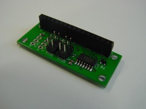
LCD
This is the documentation page for the SPI_LCD and I2C_LCD boards.
Overview
Assembly instructions
The board comes fully assembled.
Possible Configurations
The second SPI port can be used as an ICSP connector.
External resources
Datasheets
The fet: http://www.irf.com/product-info/datasheets/data/irlml2244pbf.pdf
The CPU: http://www.atmel.com/dyn/resources/prod_documents/doc8006.pdf
Additional software
Related projects
Pinout
For the SPI connector see: SPI_connector_pinout.
For the I2C connector see: I2C_connector_pinout.
LEDs
The only LED is a power indicator.
Jumper settings
There are two solder jumpers. The one between the two 6-pin SPI connectors controls the function of the SPI connector furthest from the CPU.
In the default configuration the second SPI connector is a daisy-chain connector for the SPI bus.
In the other configuration, the second SPI connector is the ICSP connector.
There is a 10 mil (very small) PCB trace in the solder jumper in the default configuration. You'll have to cut this trace to move the solderjumper to the other position. If you later decide you want the other configuration again, some solder-wick can be used to remove the solder from one position and then it can be added to the other position.
Programming
For the intro to the SPI and I2C protocols read: SPI versus I2C protocols
The board specific protocol can be found here: spi_lcd 1.3_protocol spi_lcd_1.2_protocol i2c_lcd_protocol
You should also read the General_SPI_protocol notes.
For arduino, a sample PDE is available, called ardemo_lcd.pde, also at BitWizard software download directory .
This is a demo to send things using SPI to the lcd board. The SPI routines there are applicable for LCD boards as well.
The software
Future hardware enhancements
Future software enhancements
- Lock the address. (require a sequence of commands to change the address).
Changelog
1.2
- Initial public release
