Relay
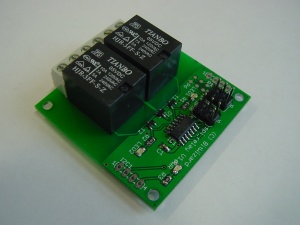
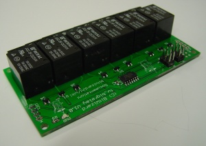
This is the documentation page for the I2C/SPI Relay and BigRelay boards. The Relay board can be bought in the BitWizard Shop. The BigRelay board can be bought here in the BitWizard shop.
Overview
The Relay board allow you to drive two relays, while the BigRelay board can drive six relays. Both of the boards have a I2C and SPI version.
Assembly instructions
None: the board comes fully assembled.
Protocol
To make the relay PCB do things, you need to send things over the SPI bus to the PCB.
The general overview of the protocol is here.
The specific commands for the relay PCB are explained on the page about the spi_dio board, as the two boards share the same protocol: DIO_protocol . The address of the BigRelay was incorrectly documented at first. The correct address is 0x9c.
For Arduino, a sample PDE is available, called ardemo_lcd.pde, also at the BitWizard software download directory .
This is a demo to send things using SPI to the lcd board. The SPI routines there are applicable for the dio and relay boards as well.
Jumper settings
The Bigrelay has a jumper on the right side of the board. It is usually marked "SV1". The pinout is as follows:
- 3 - +5V from SPI/I2C (marked "5V")
- 2 - 5V for the relays (marked "aux 5V")
- 1 - GND (marked GND)
This allows you to use the SPI/I2C 5V by installing a jumper on 2-3, or use an external powersupply by connecting the powersupply GND to pin 1 and the 5V from the powersupply to pin 2.
Additional Considerations
Each relay draws about 70mA. This means that if you have the bigrelay board, and turn on all six relays, the current draw will amount to about 400mA. If you have the board connected to a Raspberry Pi, this might stress your polyfuse on the 5V line, and/or exceed the capabilities of your powersupply. You can supply extra 5V power on the 5V lines of other connectors on the board. For example, if you have the SPI version, you can mount one of the I2C connectors and provide GND and 5V on pin 1 and 4 respectively.
Note that your extra powersupply is likely to start powering the Raspberry Pi a bit as well. (Due to the voltage drop over the polyfuse in the Raspberry Pi, the 5V on the relay board is likely to be a bit higher than that what ends up on the Pi itself.) You could consider powering the whole system through this extra powersupply, but be careful, the polyfuse on the Pi is now circumvented.
On the other hand, on the newer bigrelay boards, you can provide the power for the relays on SV1 as described above.
Default operation
By default the relays will start out in the "off" position. (i.e. a connection between the common and the "normally closed" will be present).
Power Consumption
Each relay typically consumes about 55mA. Max 70mA. So for a bigrelay with all relays "on" you need to arrange for about 400mA of power. The board uses about 8mA when idle (typ).
Pinout
For the SPI connector see: SPI_connector_pinout.
For the I2C connector see: I2C_connector_pinout.
| pin | function | remark |
|---|---|---|
| 1 | NO 1 | Normally open contact for relay 1 |
| 2 | C 1 | center connection for relay 1 |
| 3 | NC 1 | normally closed contact for relay 1 |
| 4 | NO 2 | Normally open contact for relay 2 |
| 5 | C 2 | center connection for relay 2 |
| 6 | NC 2 | normally closed contact for relay 2 |
| Only for BigRelay: | ||
| 7 | NO | Normally open contact for relay 3 |
| 8 | C | center connection for relay 3 |
| 9 | NC | normally closed contact for relay 3 |
| 10 | NO | Normally open contact for relay 4 |
| 11 | C | center connection for relay 4 |
| 12 | NC | normally closed contact for relay 4 |
| 13 | NO | Normally open contact for relay 5 |
| 14 | C | center connection for relay 5 |
| 15 | NC | normally closed contact for relay 5 |
| 16 | NO | Normally open contact for relay 6 |
| 17 | C | center connection for relay 6 |
| 18 | NC | normally closed contact for relay 6 |
Controlling the relays of Relay or BigRelay
With the 10 register you can turn everything on or off. It is a bitmask register. (bw_tool uses hexadecimal numbers, so add the values for the diffrent relays together, 1,2,4,8, 10, 20 for relays 1-6.)
bw_tool -s 50000 -a 9c -W 10:0:b #Everything off
bw_tool -s 50000 -a 9c -W 10:1:b #Relay 1 on
bw_tool -s 50000 -a 9c -W 10:20:b #Relay 6 on
You can use register 20 till 25 to turn every single relay on or off.
bw_tool -s 50000 -a 9c -W 20:0:b #Relay 1 off
bw_tool -s 50000 -a 9c -W 25:1:b #Relay 6 on
Which method you use is up to you. If your program "knows" the state of all the relays, using register 0x10 may be easier. But if say you have one program controlling one relay and another program controlling another, using the 20-25 registers is probably easier.
LEDs
There is one power led.
On the regular relay board are two LEDs near each of the relays indicating the state of the relays. The BigRelay board doesn't have indication LEDs.
Related projects
External resources
Datasheets
5A variant: Songle SRD-05VDC
10A variant: Omron G5LE-1
Additional software
Changelog
1.0
- Initial public release

