Blog 17
2 Wheel controlled car
I made this on the Raspbery Pi for the stepper motor and for 'electric wheels'. This is just an example how to do it with 2 wheels but you can also of course easily change it to 4 wheels.
Connecting a USB WIFI Adapter on your Raspberry Pi
For both versions of the car it is needed that the raspbery pi can contact with the pc without a cable. Otherwise the car will the whole time be hanging on the cable. For this we use a Dongle, for this I will make a quick and easy tutorial for how to get it to work:
First you get your dongle and just put it one raspberry pi USB port.
To look if your Raspberry Pi sees your dongle you have to give the command:
dmesg | more
When you gave the command you will get a big list when you scroll down with the space button you will something like this. That shows that the Raspberry Pi has seen the USB wifi adapter. (You can leave the code with q or just keep scrolling down until the end.)
[    3.023180] usb 1-1.4: new high-speed USB device number 4 using dwc_otg
[    3.509915] usb 1-1.4: New USB device found, idVendor=148f, idProduct=76 01
[    3.519408] usb 1-1.4: New USB device strings: Mfr=1, Product=2, SerialNumber=3
[    4.287414] udevd[177]: starting version 175
To than change the network settings to let the dongle work. You have to change the network interface:
nano /etc/network/interfaces
In there you have to change the files into:
auto lo
iface lo inet loopback
iface eth0 inet dhcp

allow-hotplug wlan0
auto wlan0

iface wlan0 inet dhcp
   wpa-ssid "YOUR WIFI NAME"
   wpa-psk "YOUR WIFI PASSWORD"
The only thing you have to change is the caps locked text, where you have to obviously put in your wifi name and password.
After this you have to do:
sudo ifconfig
You then should find in the list one called wlan0.
wlan0     Link encap:Ethernet  HWaddr e8:4e:06:2f:70:ca
          inet addr:192.168.234.218  Bcast:192.168.234.0  Mask:255.255.255.0
          UP BROADCAST RUNNING MULTICAST  MTU:1500  Metric:1
          RX packets:2800336 errors:0 dropped:0 overruns:0 frame:0
          TX packets:26543 errors:0 dropped:0 overruns:0 carrier:0
          collisions:0 txqueuelen:1000
          RX bytes:399260993 (380.7 MiB)  TX bytes:3389882 (3.2 MiB)
You than have to save/remember the name of the IP address, which you can read in the second row. Mine is:
inet addr:192.168.234.218
After that
reboot
And connect with your raspberry pi:
ssh pi@192.168.234.218
And now your raspberry pi should work with your dongle.
Stepper motor version
Hardware I used on my Raspberry Pi:
- One RPi_UI board | (User Interface)
- Two 7FETs | (7FETs)
- Two Jumper cables M-F
- Two IDC cable 6 pin
- Two 28BYJ-48 Stepper Motor
Programming:
- Bash
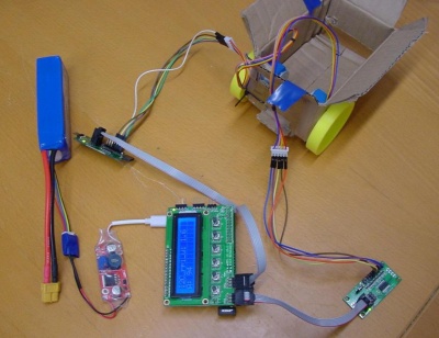
The full car just went to be a carton box, with everything attached to it with tieraps.
3D printed wheels code
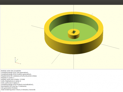
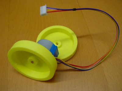
I made the wheels in OpenSCAD and let them be printed out on a 3d printer. The diameter of the wheel is 60mm and is 12mm high. The hole in the middle was made to put in the 28BYJ-48 Stepper Motor. The OpenSCAD code:
$fs=0.2; $fa=2;

module stepperas(d=5, l=25, t=3)
{
  difference()
  {
    cylinder (r=d/2 , h=l);
translate ([t/2, -5, -1])   cube([10, 20, l+2]);
translate ([-t/2-10, -5, -1])  cube([10, 20, l+2]);

  }
}

difference()
{
  union () {
    difference () {
      cylinder (r=60/2 ,h=12);
      translate ([0, 0, 1.5])
        cylinder (r=50/2, h=20);
    }
    cylinder (r=6,h=6);
  }

  translate ([0, 0, -1])
    stepperas(5.2, 20, 3.2);
}
The result of the OpenSCAD code (Press F5 to see it in OpenSCAD):
The Result in the real world:
Code
Here is a list of the commands one of each other, that you could send to the stepper motor.
#!/bin/bash

#Address=spi0   address2=spi1
Address="bw_tool -s 50000 -a 88"
Address2="bw_tool -S -D /dev/spidev0.1 -a 88"

#800 is rotating a full circle
Rot=800
Target=`$Address -R 41:i`

Speed1=0x200
Speed2=0x100
#Speed3=0x50
#Speed4=0xff

#Turn left
$Address -W 43:$Speed1:b
$Address -W 42:$Rot:i
$Address2 -W 43:$Speed2:b
$Address2 -W 42:$Rot:i
sleep 10

#Turn Right
$Address -W 43:$Speed2:b
$Address -W 42:$Rot:i
$Address2 -W 43:$Speed1:b
$Address2 -W 42:$Rot:i
sleep 10

#Go Forwards
$Address -W 43:$Speed2:b
$Address -W 42:-$Rot:i
$Address2 -W 43:$Speed2:b
$Address2 -W 42:$Rot:i
sleep 10

#Go Backwards
$Address -W 43:$Speed2:b
$Address -W 42:$Rot:i
$Address2 -W 43:$Speed2:b
$Address2 -W 42:-$Rot:i
sleep 10

#Spin right
$Address -W 43:$Speed2:b
$Address -W 42:$Rot:i
$Address2 -W 43:$Speed1:b
$Address2 -W 42:-$Rot:i
sleep 10

#Spin left
$Address -W 43:$Speed2:b
$Address -W 42:-$Rot:i
$Address2 -W 43:$Speed1:b
$Address2 -W 42:$Rot:i
The raspberry pi is connected with a battery so that it doesn't need a usb cable from the power plug to give it power.
The connection of the 7FETS is the same as in blog 15 and in blog 16 you can read also read how to get the second 7FETs to work. Cables blue till orange from the stepper motor go to pin 2,4,6 and as last 8. The power cable(red) from the stepper motor goes to pin 1.
'Electric wheels' version
Hardware I used on my Raspberry Pi:
- One RPi_UI board | (User Interface)
- One Motor | (Motor)
- One Cable, 4 Pin (I2C), F-F
- Two single Jumper cables M-M
- Two electric wheels
- Soft cables ( To connect to the motor and the wheels )
- One dongle
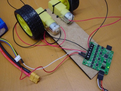
To put the wheels on the board: I just made some holes and put some tieraps around the board to hold the electric wheels.
Cable connection:
| pin | function | cable |
|---|---|---|
| 1 | Output B1 | Black (Connected with right wheel down) |
| 2 | Output B2 | Red (Connected with right wheel up) |
| 3 | Output A1 | Black (Connected with left wheel down) |
| 4 | Output A2 | Red (Connected with left wheel top) |
| 5 | GND | White Jumper Cable M-M (Connected with the ground from the battery) |
| 6 | Vin | Red Jumper Cable M-M (Connected with the power from the battery) |
The cables and jumper cables can of course be different colors, but I told the color for the images. The reason I used the jumper cable M-M is because it is easier to put in the battery.
( The cable on the bottom right is a 4 Pin (I2C) Cable, F-F. That is to connect the motor with the Raspberry Pi. )
Programming
Programmed in:
- Bash
Script:
#!/bin/bash

#Wheel A left forward
#Wheel B Right forward

# X is forwards - Y is backwards
#Wheels at front
#20  A backwards
#21  A forwards
#22  A stop
#30  B backwards
#31  B forwards
#32  B stop

Address="bw_tool -I -D /dev/i2c-1 -a 90"
Speed="80"
Speed2="40"

while true; do
  BUTTON=`bw_tool -I -D /dev/i2c-1 -a 94 -R 30:b`

  if [ $BUTTON  = "20" ]; then
  #Car going forwards
  $Address -W 21:$Speed:b
  $Address -W 31:$Speed:b
  fi

  if [ $BUTTON  = "10" ]; then
  #Car going backwards
  $Address -W 20:$Speed:b
  $Address -W 30:$Speed:b

  if [ $BUTTON  = "08" ]; then
  #Car going left
  $Address -W 21:$Speed2:b
  $Address -W 31:$Speed:b
  fi

  if [ $BUTTON  = "04" ]; then
  #Car going right
  $Address -W 21:$Speed:b
  $Address -W 31:$Speed2:b
  fi

  if [ $BUTTON  = "02" ]; then
  #Car Stop
  $Address -W 22:$Speed:b
  $Address -W 32:$Speed:b
  fi

  if [ $BUTTON  = "01" ]; then
  exit
  fi

  sleep 1
done
Other movements:
#Spinning right
bw_tool -I -D /dev/i2c-1 -a 90 -W 20:80:b
bw_tool -I -D /dev/i2c-1 -a 90 -W 31:80:b

#Spinning left
bw_tool -I -D /dev/i2c-1 -a 90 -W 21:80:b
bw_tool -I -D /dev/i2c-1 -a 90 -W 30:80:b
I think the code pretty much explains itself with the extra info I have given it. I used the push buttons as example of how it could be used. All the protocols can been found in Motor protocol.
Useful links
- Working with a 7FETs Stepper motors Blog 15
- Working with multiple 7FETs Stepper motors Blog 16
- Blog list ( Overview of all my posts )
- Motor protocol
- OpenSCAD documentation


