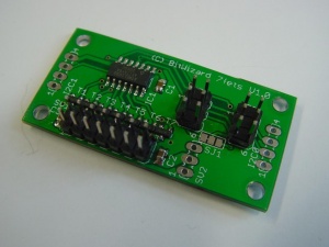
7FETs
This is the documentation page for the SPI_6FETs board.
Overview
The board has 7 fets that allow you to pull a pin of a load low. You would normally tie the other end of your load directly to the powersupply.
About 1A per output should be possible. Maximum voltage is 20V.
You will have to provide your own protection circuits if you are going to drive inductive loads (like a motor).
Assembly instructions
Possible Configurations
External resources
Datasheets
Additional software
Related projects
Pinout
LEDs
Jumper settings
The connector SV2 allows you to connect the "powersource".
You can chose two configurations: You can use pin 1-2 as ground and power. You can connect up to 15V (*) to pin 2 referenced to GND on pin 1.
(*) The datasheet for the used transistors mentions "20V", but is is always prudent to keep some margin.
If you want 5V as the powersource, you could put a jumper on pin 2-3. In that case you will have to be aware that you're using the 5V power from the rest of the system. This will be limited by e.g. USB power limits, other devices on the SPI bus, cable thickness and connector capability. But for low-current 5V applications this might be useful.
Programming
The software
Default operation
Future hardware enhancements
Future software enhancements
Changelog
1.0
- Initial public release
