Difference between revisions of "Raspberry Pi User Interface with 16 x 2 LCD with a console serial cable"
From BitWizard WIKI
Cmaxwell au (talk | contribs) |
|||
| Line 1: | Line 1: | ||
| − | |||
| − | + | ||
| + | Connecting the rpi_ui to a USB to TTL console cable. | ||
The console cable manual show the following connection diagram: | The console cable manual show the following connection diagram: | ||
| Line 7: | Line 7: | ||
[[File:RPI_Console_pins.png]] | [[File:RPI_Console_pins.png]] | ||
| − | + | Our boards break out the uart pins on a 4-pin uart connector. | |
| + | |||
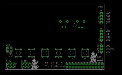
| + | Here is a diagram (top view) of the rpi_ui. Even if it might show the 16x2, the 20x4 board has the pins in exactly the same order. | ||
| + | [[File:Rpi_ui_docu.png|none|thumb|500px|alt=The RPi_UI PCB|The RPi_UI PCB]] | ||
| + | |||
| + | So to connect things up, | ||
| + | Connect the black GROUND connector to the GND pin. The one nearest the I2C connector. | ||
| + | connect the green RXD cable to the next pin and | ||
| + | Connect the white TXD cable to the third pin. | ||
| + | |||
| + | You can leave the red VCC connector unconnected. | ||
Revision as of 13:33, 16 January 2013
Connecting the rpi_ui to a USB to TTL console cable.
The console cable manual show the following connection diagram:
Our boards break out the uart pins on a 4-pin uart connector.
Here is a diagram (top view) of the rpi_ui. Even if it might show the 16x2, the 20x4 board has the pins in exactly the same order.
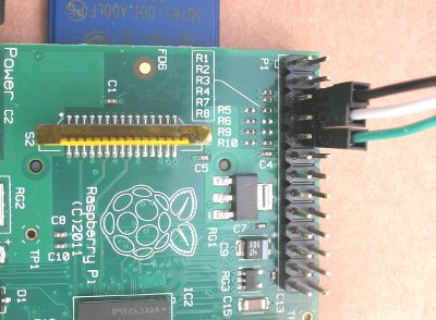
So to connect things up, Connect the black GROUND connector to the GND pin. The one nearest the I2C connector. connect the green RXD cable to the next pin and Connect the white TXD cable to the third pin.
You can leave the red VCC connector unconnected.


