File list
Jump to navigation
Jump to search
This special page shows all uploaded files.
| Date | Name | Thumbnail | Size | User | Description | Versions |
|---|---|---|---|---|---|---|
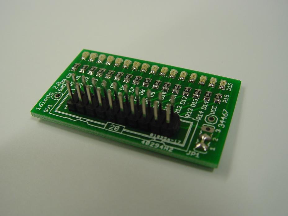
| 19:42, 25 January 2012 | 16-LEDs.jpg (file) |  |
49 KB | Tom | 1 | |
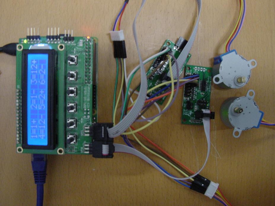
| 18:33, 6 November 2015 | 27FETsStepperMotors.jpg (file) |  |
79 KB | Cartridge1987 | 2 7FETs connected with the raspberry pi through spi cables. On the 2 7FETs are stepper motors connected. | 1 |
| 18:36, 6 November 2015 | 27FETsStepperMotorsV.jpg (file) |  |
78 KB | Cartridge1987 | Vertical picture of the 2 Stepper motors being connected with 2 7Fets to a Raspberry Pi. | 1 |
| 15:35, 29 June 2012 | 2regulators.jpg (file) |  |
1.07 MB | Tom | 1 | |
| 13:40, 17 November 2015 | 3DPrintedWheel.jpg (file) |  |
52 KB | Cartridge1987 | The 3D printed wheel that was made for the 28BYJ-48 Stepper Motor. Read how it is made in blog 17 | 1 |
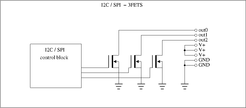
| 14:55, 14 January 2014 | 3fets.png (file) |  |
11 KB | Rew | 3fets board block diagram. | 1 |
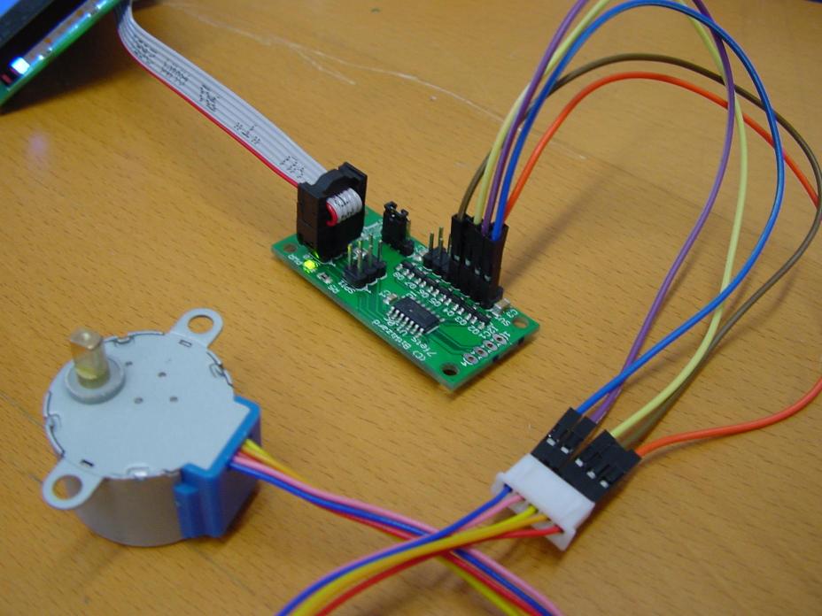
| 11:50, 29 October 2015 | 7fetsStepper.jpg (file) |  |
79 KB | Cartridge1987 | A 28BYJ-48 Stepper Motor connected with a 7fets board. | 1 |
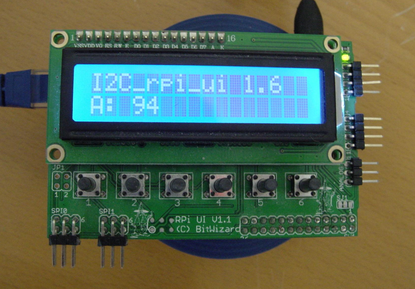
| 10:53, 11 September 2015 | 94.png (file) |  |
2.06 MB | Cartridge1987 | I2c_RPI_UI 1.6A A: 94 | 1 |
| 16:12, 16 January 2012 | Afb000.jpg (file) |  |
89 KB | Tom | Reupload, due to server side problems | 3 |
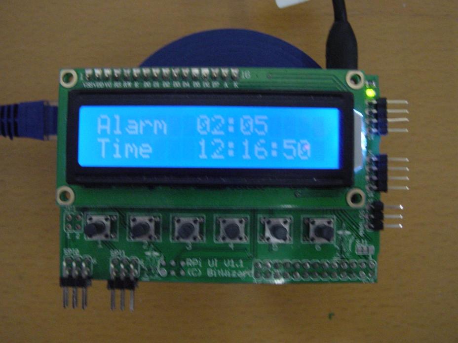
| 13:22, 21 October 2015 | AlarmMenuStart.jpg (file) |  |
65 KB | Cartridge1987 | This image shows the Alarm given and the time on the Alarm Menu. | 1 |
| 09:50, 22 October 2015 | AlarmMinSettings.jpg (file) |  |
122 KB | Cartridge1987 | In this image it shows what should display if you are setting up the minutes of the alarm. | 1 |
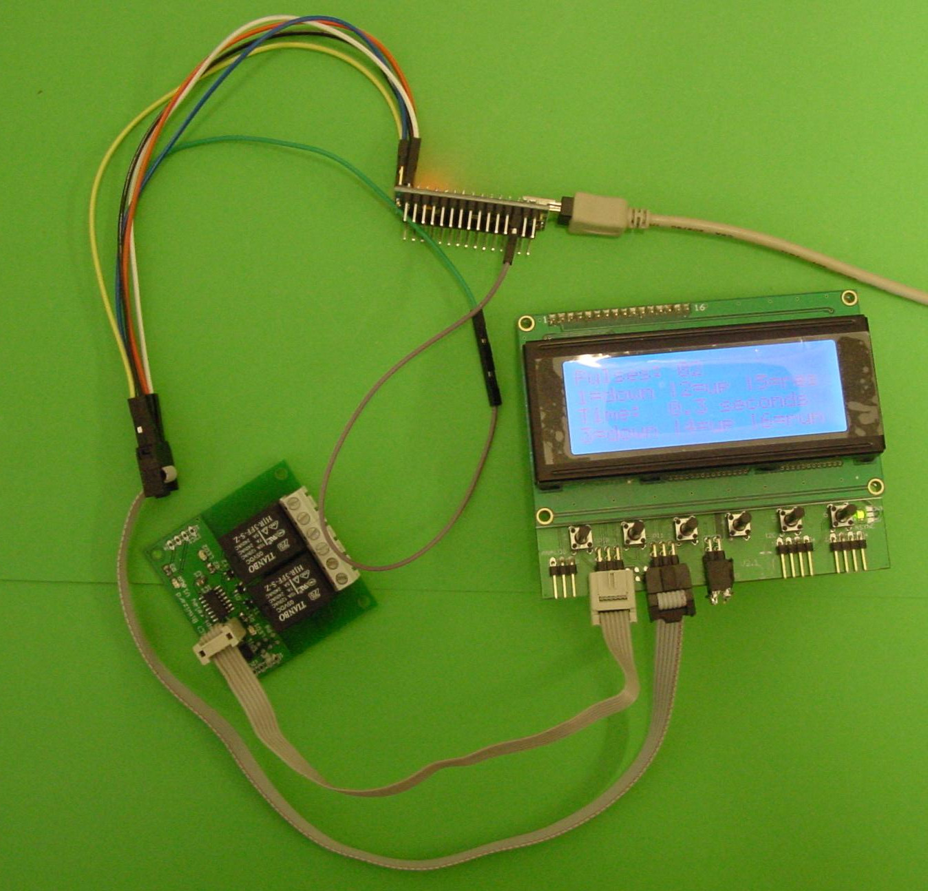
| 17:30, 23 October 2015 | ArduinoBigRelay.jpg (file) |  |
147 KB | Cartridge1987 | Connection from the arduino, the lcd and the bigrelay. | 1 |
| 17:02, 24 December 2015 | ArduinoPWMMeter.jpg (file) |  |
95 KB | Cartridge1987 | Setup for the DIO Stepper motor - Clock & Timer. Appears in Blog 22 | 1 |
| 11:33, 22 January 2016 | Arduinorelay.jpg (file) |  |
351 KB | Cartridge1987 | 1 | |
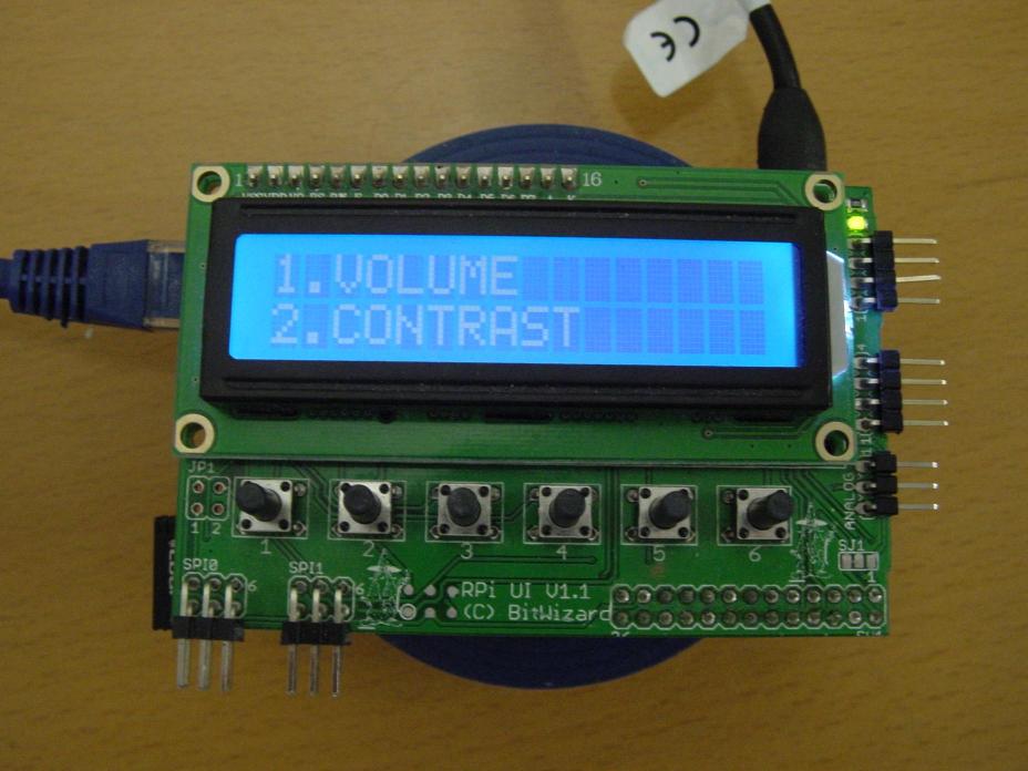
| 11:50, 19 November 2015 | BacklightHigh.jpg (file) |  |
75 KB | Cartridge1987 | 1 | |
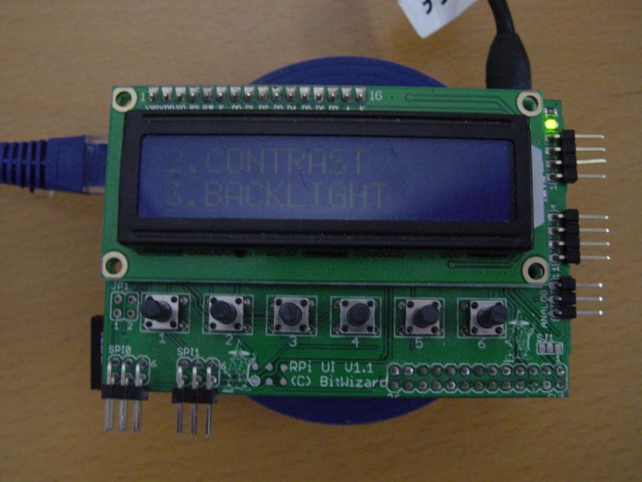
| 11:50, 19 November 2015 | BacklightLow.jpg (file) |  |
68 KB | Cartridge1987 | 1 | |
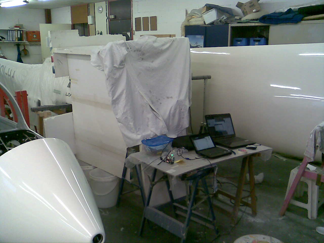
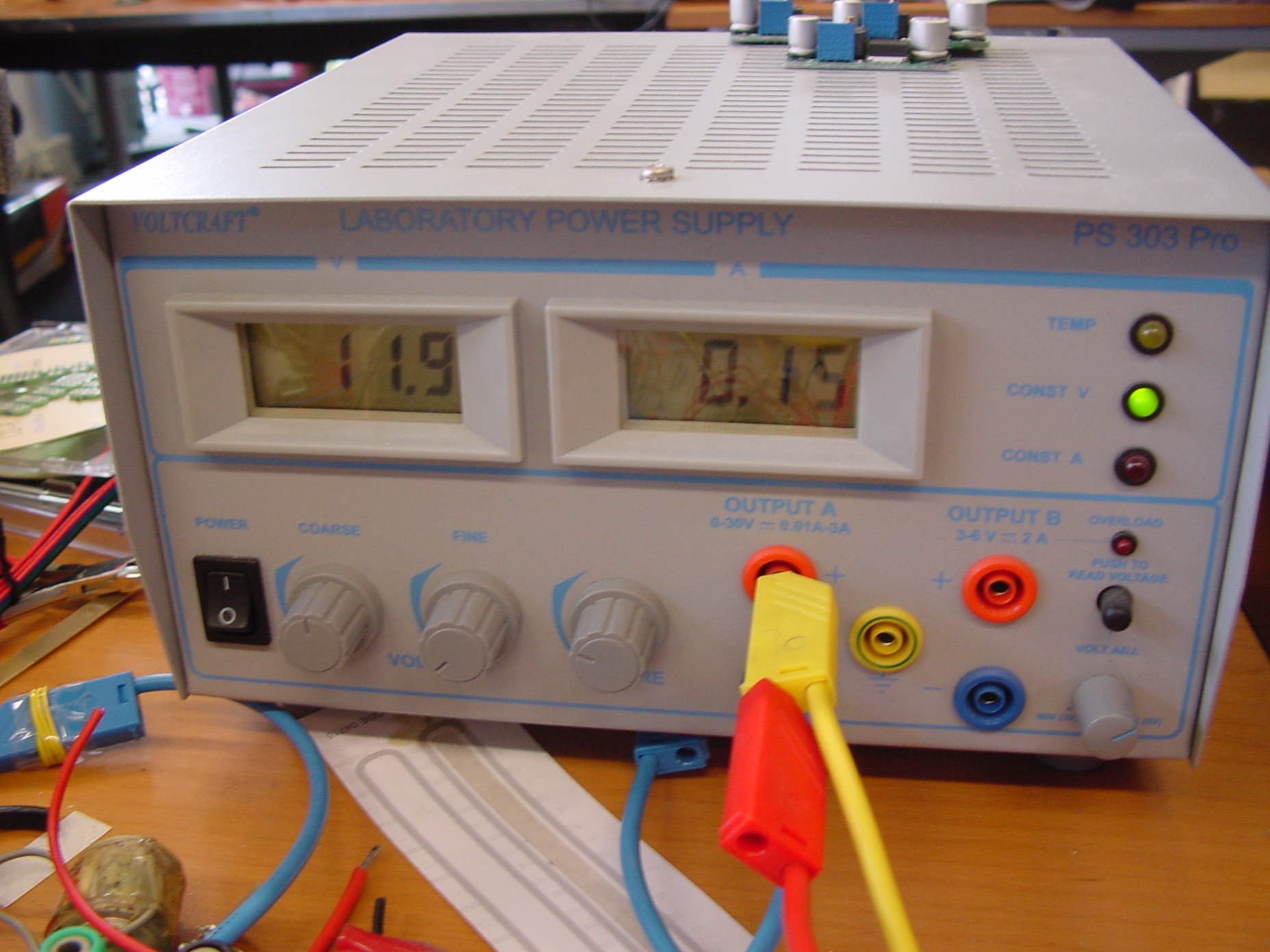
| 15:36, 29 June 2012 | Benchtop.jpg (file) |  |
972 KB | Tom | 1 | |
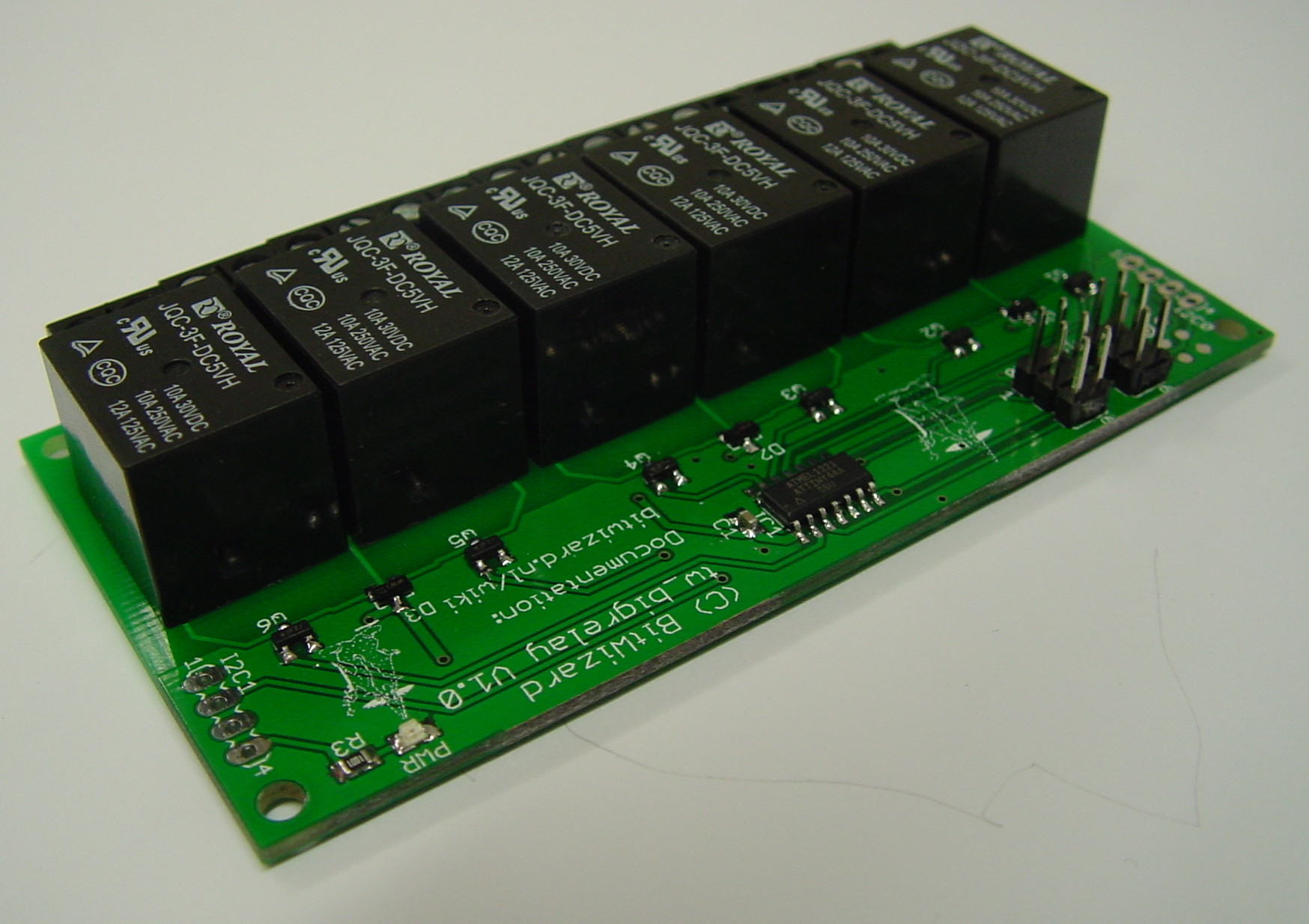
| 15:47, 21 July 2014 | Bigrelay.jpg (file) |  |
343 KB | Rijk | 1 | |
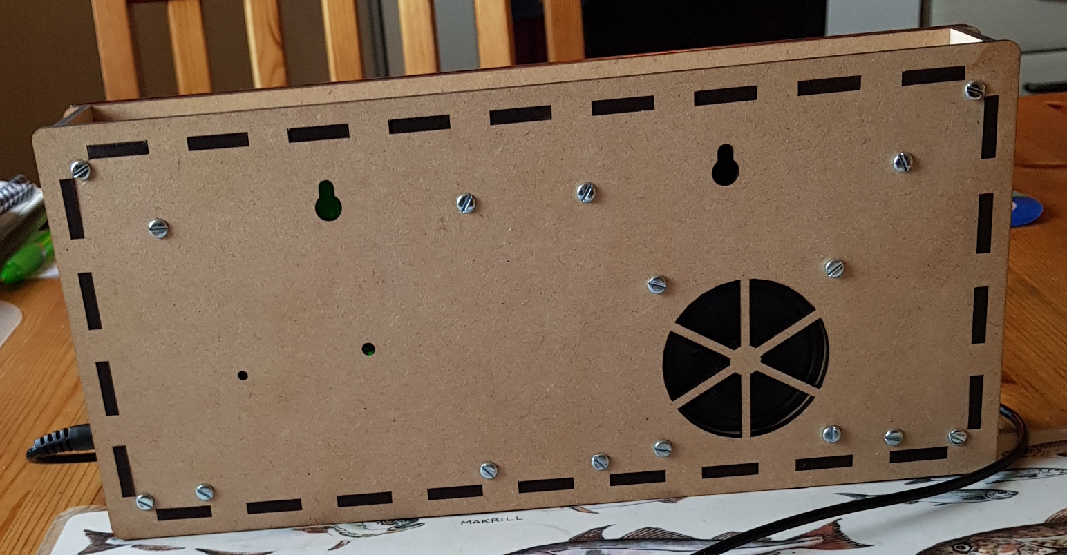
| 21:23, 2 April 2018 | Bridgeclock AVR.jpg (file) |  |
471 KB | Rew | 1 | |
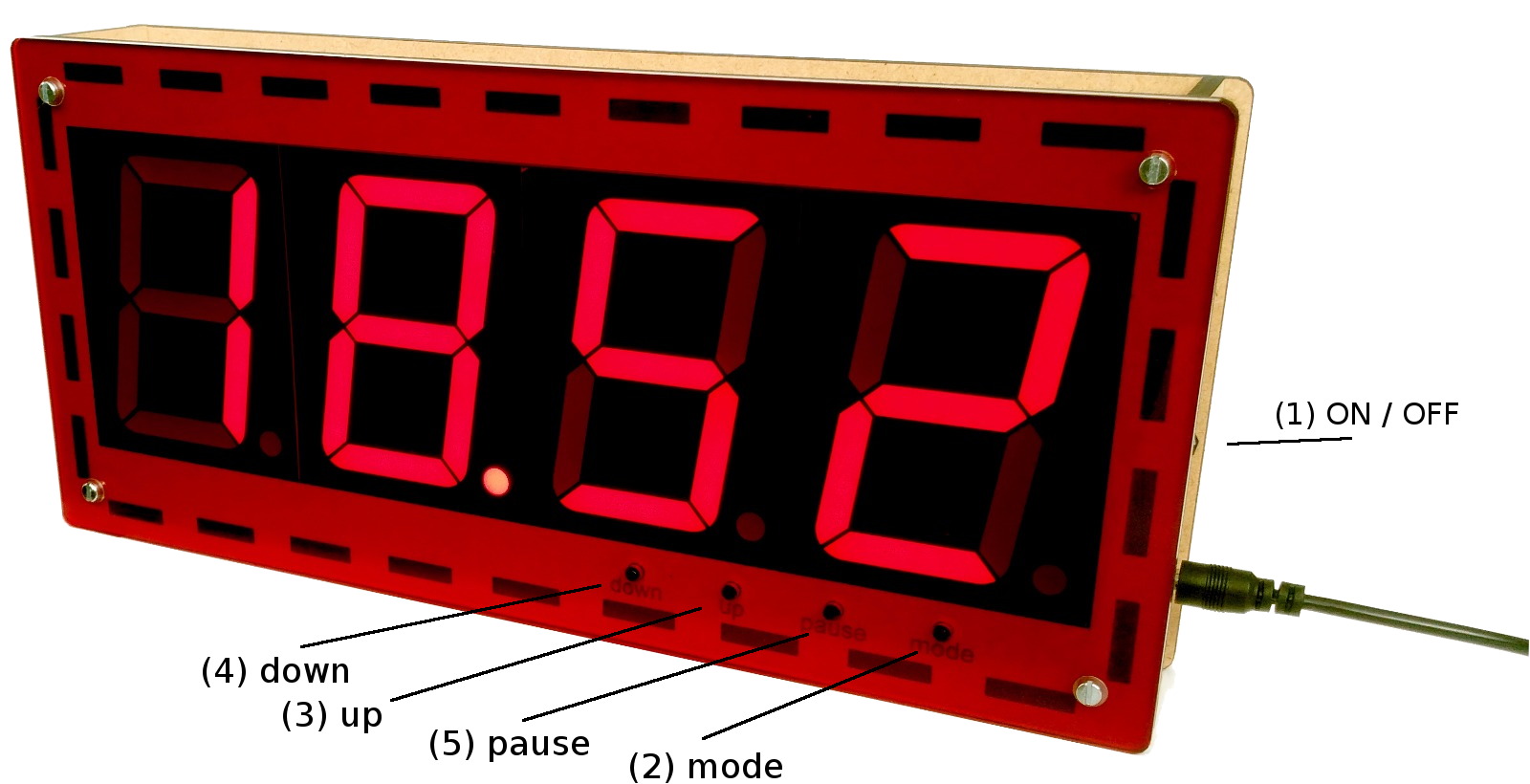
| 15:31, 24 August 2017 | Bridgeklok EN.png (file) |  |
693 KB | Daniel L | 1 | |
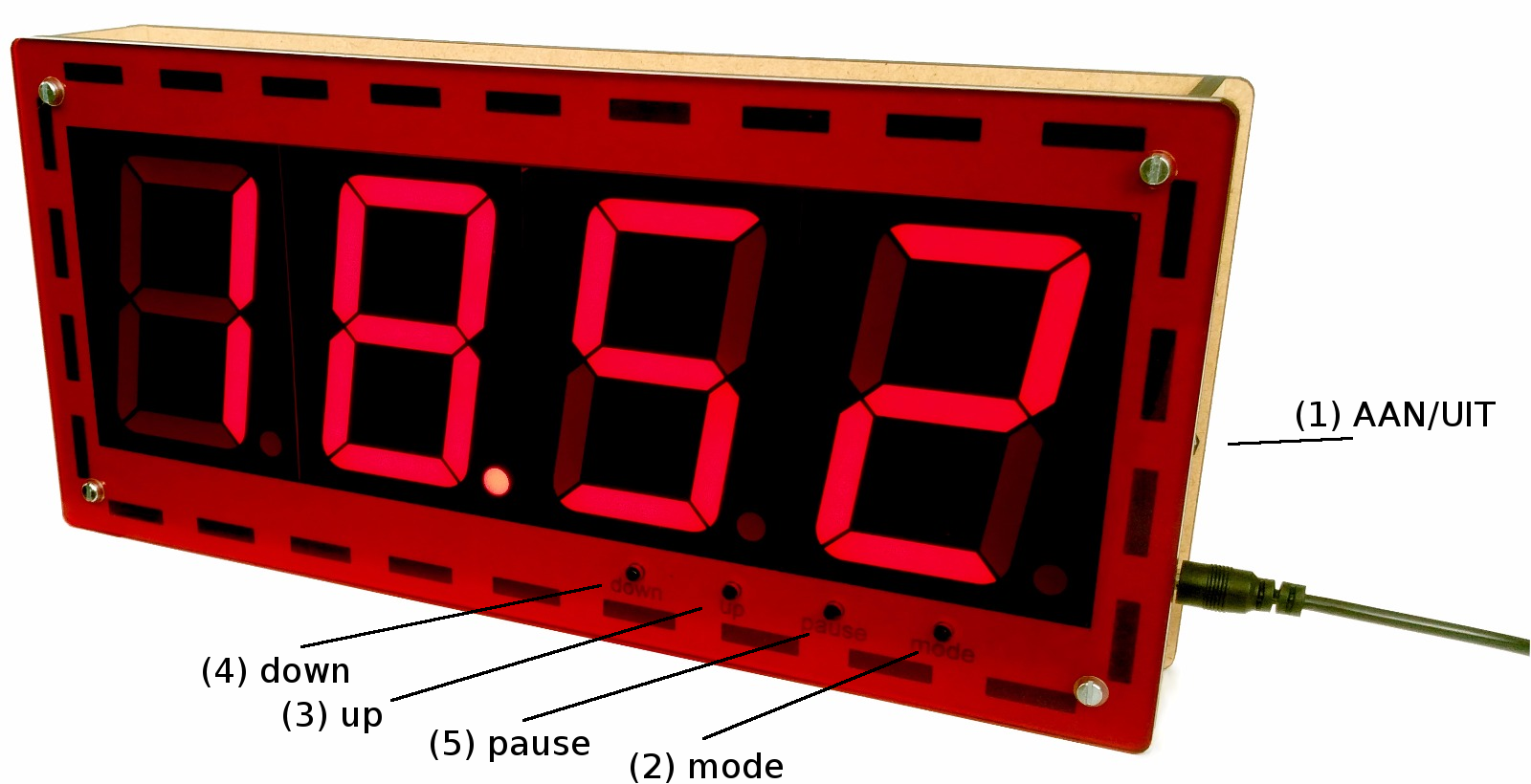
| 14:41, 12 June 2017 | Bridgeklok edit.png (file) |  |
729 KB | Rew | Bridgeklok | 1 |
| 10:44, 17 September 2015 | CPU&GPU.jpg (file) |  |
86 KB | Cartridge1987 | This image shows the temperature of the cpu and gpu from the raspberry pi printed on the RPi_UI board. | 1 |
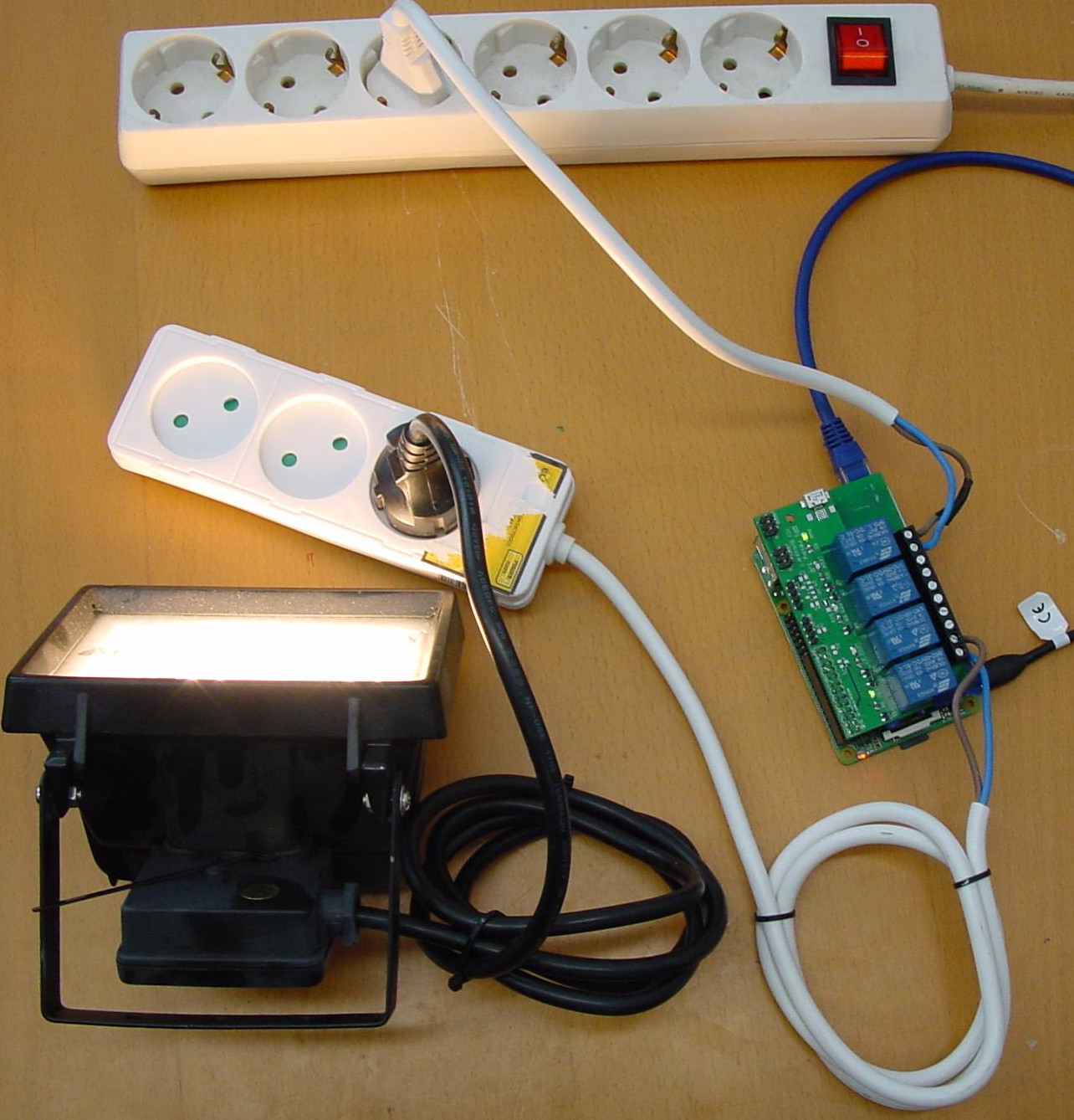
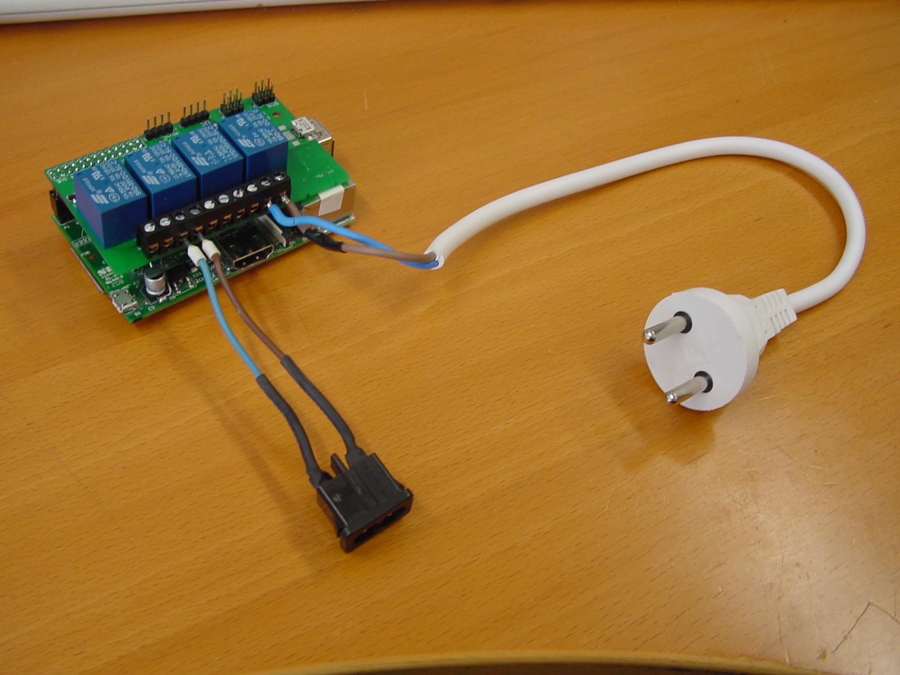
| 11:58, 11 September 2015 | ConnectionLampOn.jpg (file) |  |
365 KB | Cartridge1987 | In this image you see that the lamp is on, because of the Raspberry Relay pin being activated. | 1 |
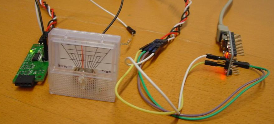
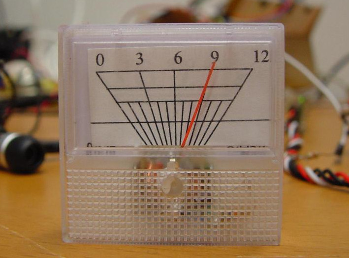
| 13:06, 17 December 2015 | DCDIO.jpg (file) |  |
107 KB | Cartridge1987 | DC meter connected with the DIO and RPI ui for Blog 21 | 1 |
| 11:08, 17 December 2015 | DClock.jpg (file) |  |
94 KB | Cartridge1987 | Made for Blog 21 | 1 |
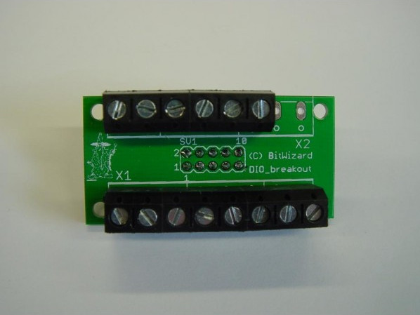
| 14:10, 10 December 2015 | DIO breakout.jpg (file) |  |
39 KB | Cartridge1987 | 1 | |
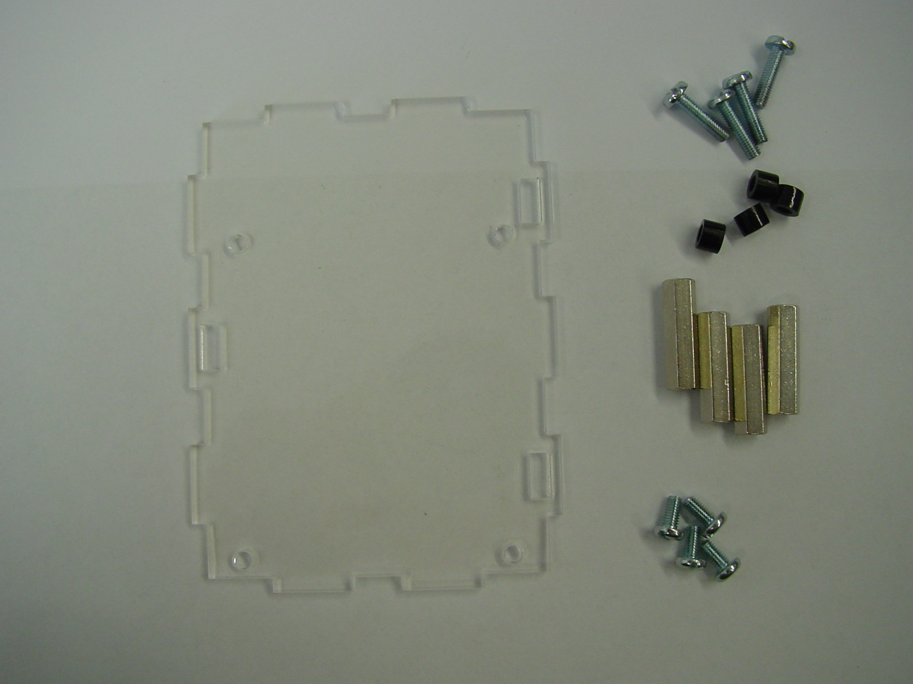
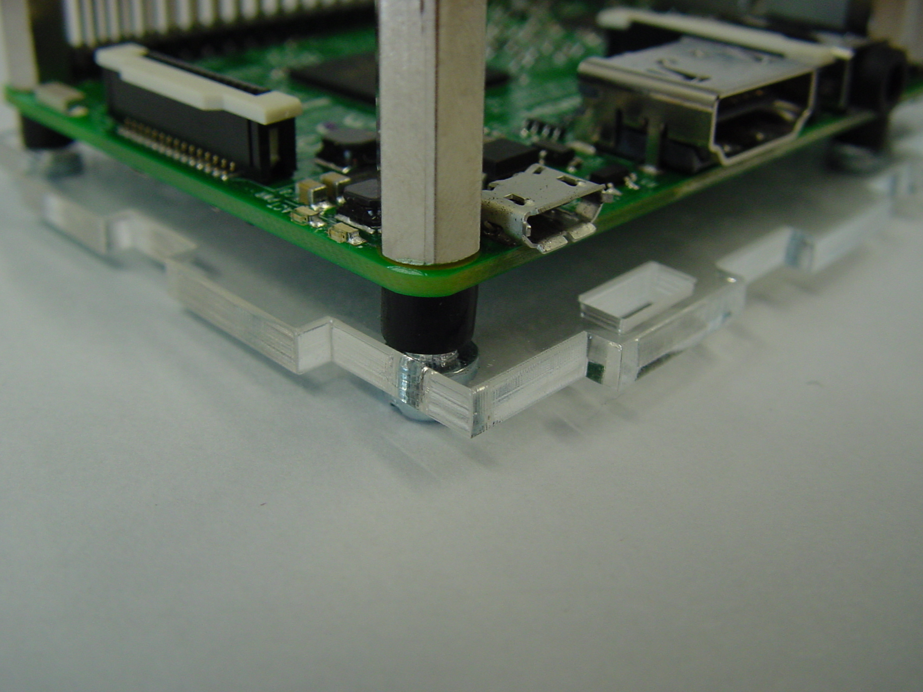
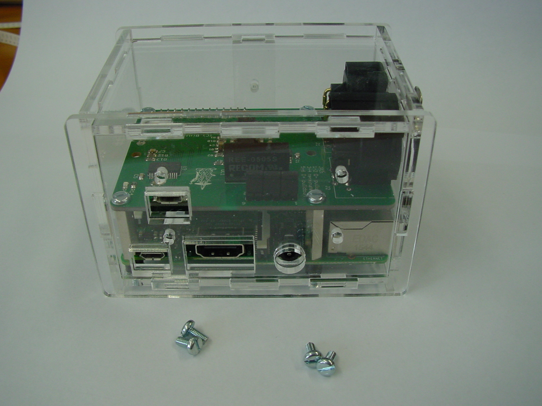
| 15:25, 6 May 2016 | DMX case 1.jpg (file) |  |
955 KB | Sjoerd | 2 | |
| 15:34, 6 May 2016 | DMX case 10.jpg (file) |  |
1.03 MB | Sjoerd | 1 | |
| 15:34, 6 May 2016 | DMX case 11.jpg (file) |  |
1 MB | Sjoerd | 1 | |
| 15:35, 6 May 2016 | DMX case 12.jpg (file) |  |
1.01 MB | Sjoerd | 1 | |
| 15:35, 6 May 2016 | DMX case 13.jpg (file) |  |
1,006 KB | Sjoerd | 1 | |
| 15:26, 6 May 2016 | DMX case 2.jpg (file) |  |
1,013 KB | Sjoerd | 2 | |
| 15:27, 6 May 2016 | DMX case 3.jpg (file) |  |
1,020 KB | Sjoerd | 2 | |
| 15:28, 6 May 2016 | DMX case 4.jpg (file) |  |
1,006 KB | Sjoerd | 2 | |
| 15:28, 6 May 2016 | DMX case 5.jpg (file) |  |
968 KB | Sjoerd | 2 | |
| 15:32, 6 May 2016 | DMX case 6.jpg (file) |  |
1,009 KB | Sjoerd | 2 | |
| 15:32, 6 May 2016 | DMX case 7.jpg (file) |  |
968 KB | Sjoerd | 2 | |
| 15:33, 6 May 2016 | DMX case 8.jpg (file) |  |
964 KB | Sjoerd | 2 | |
| 15:34, 6 May 2016 | DMX case 9.jpg (file) |  |
1.03 MB | Sjoerd | 3 | |
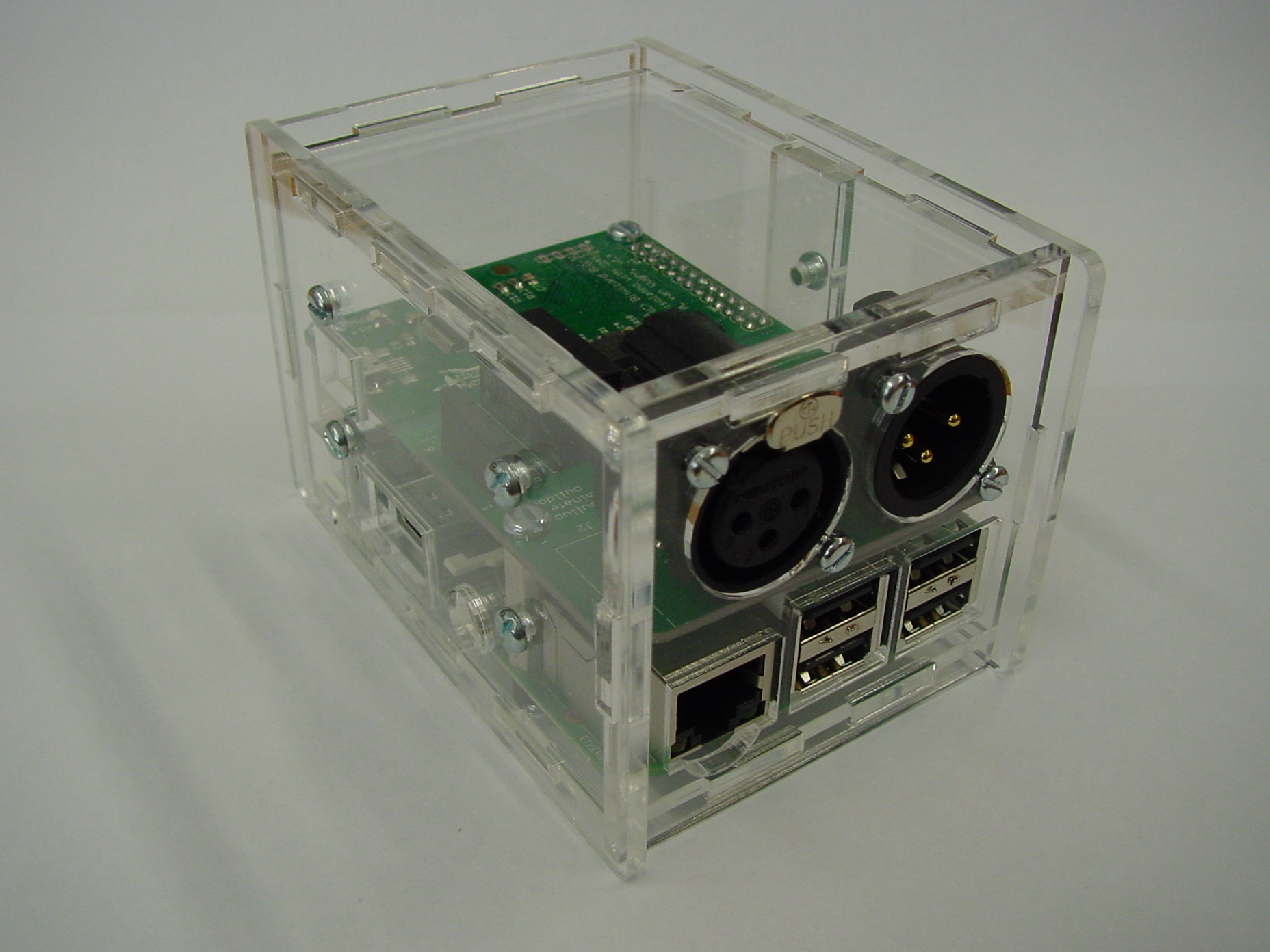
| 15:38, 6 May 2016 | DMX case complete.jpg (file) |  |
1,013 KB | Sjoerd | 1 | |
| 15:22, 5 June 2012 | DSC04653.JPG (file) |  |
979 KB | Tom | 1 | |
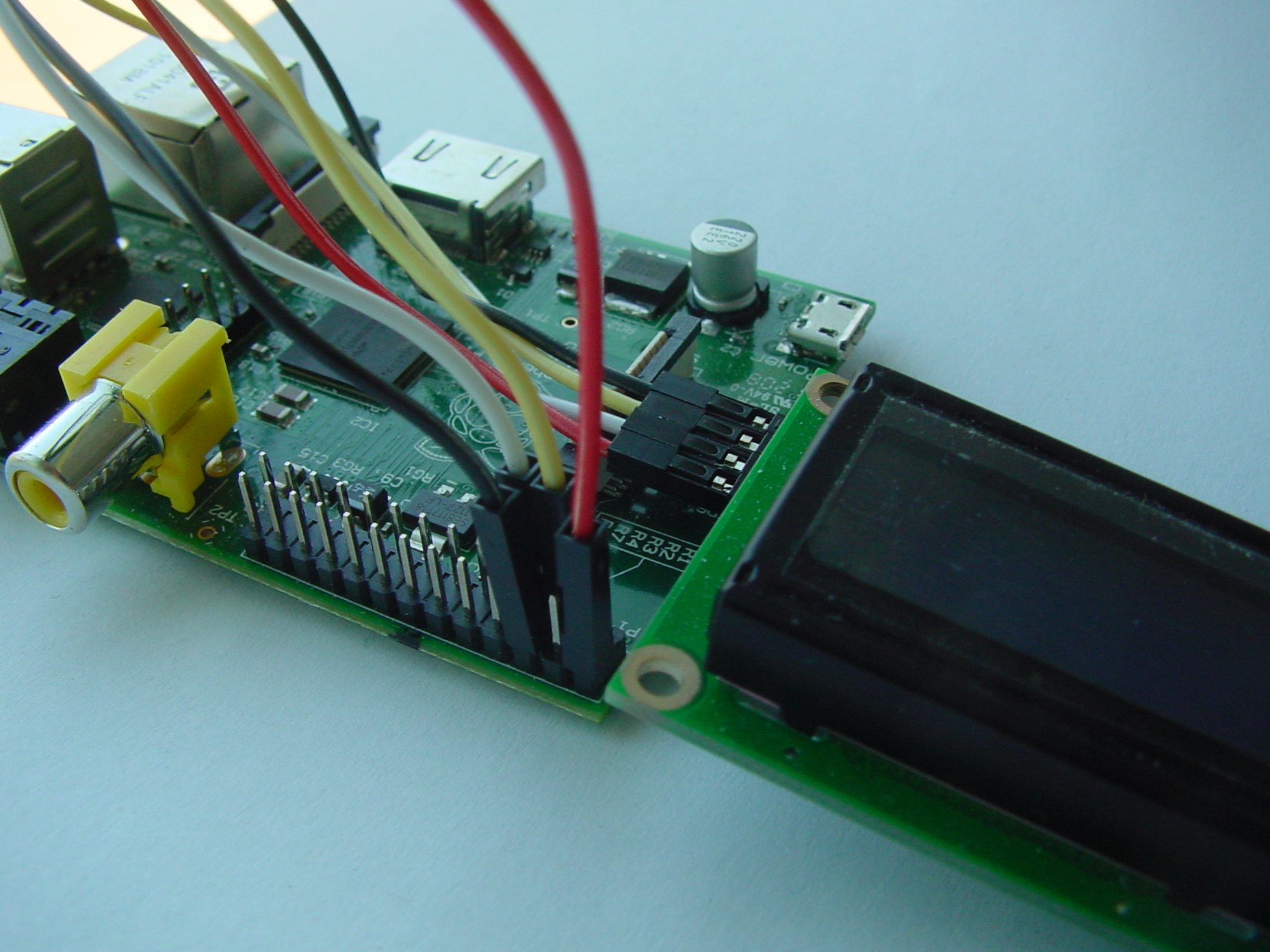
| 11:16, 5 September 2012 | DSC04800.JPG (file) |  |
987 KB | Rew | Connecting an I2C board without rpi_serial. | 1 |
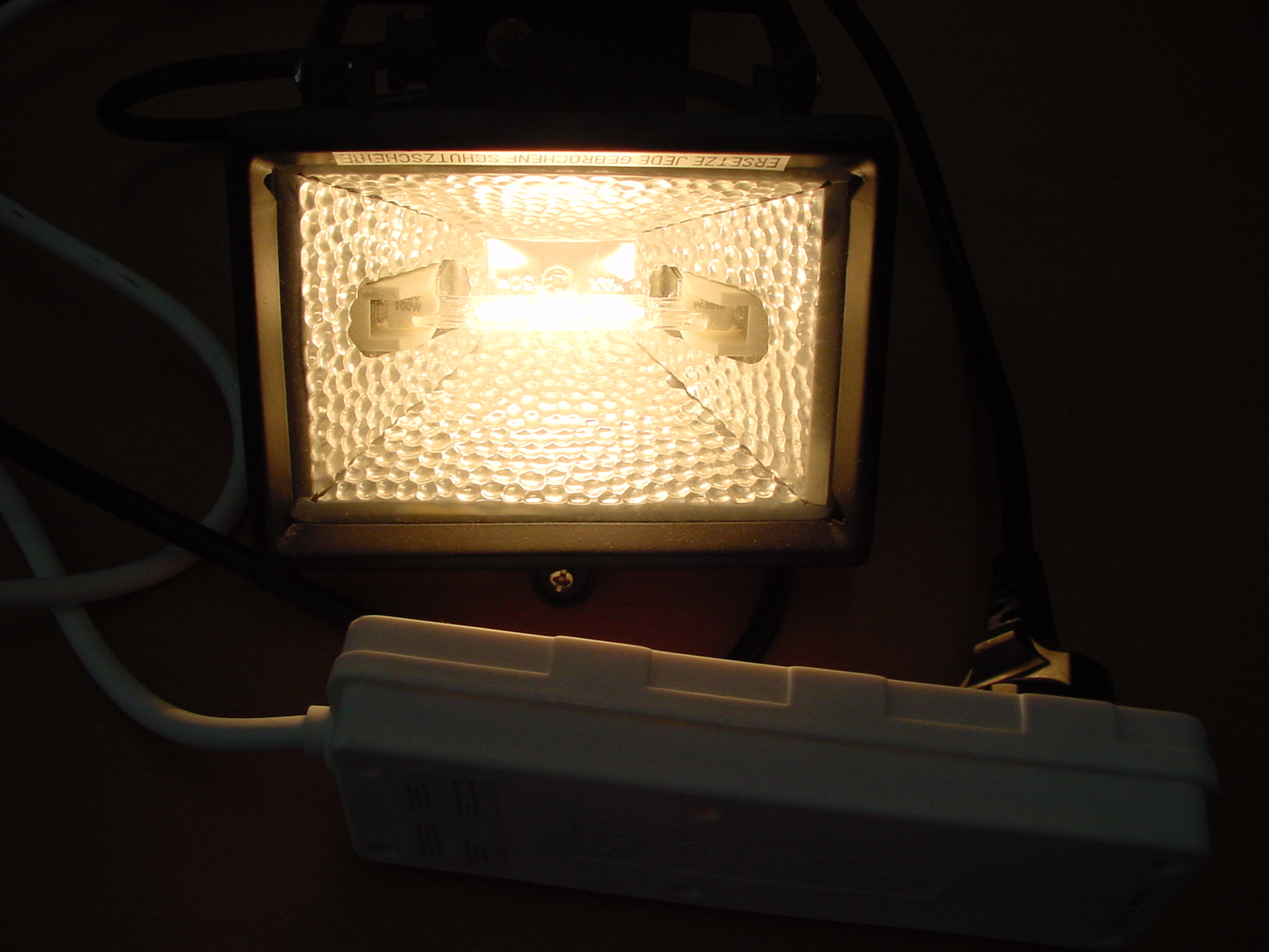
| 11:45, 11 September 2015 | DSC05964.JPG (file) |  |
960 KB | Cartridge1987 | In this images my eyes got burned, because the amount of light of the lamp. | 1 |
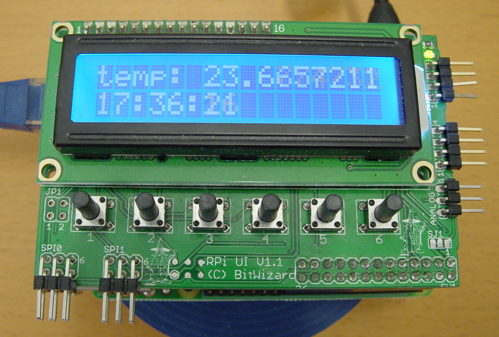
| 11:02, 11 September 2015 | DSC05993TSE.png (file) |  |
2.61 MB | Cartridge1987 | In this image RPi_UI board(Raspberry Pi Interface) is used to show the time and the temperature of it's environment. | 1 |
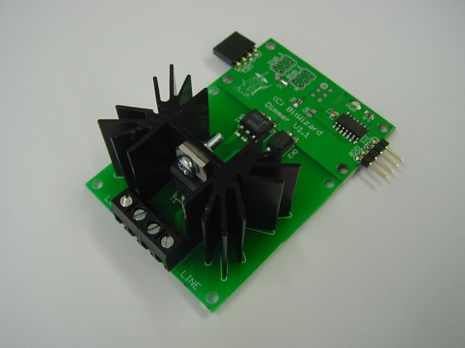
| 11:50, 9 July 2014 | Dimmer small.jpg (file) |  |
40 KB | Rijk | Bitwizard I2C Dimmer | 1 |
| 16:22, 27 August 2014 | Dsc05646 small.jpg (file) |  |
219 KB | Rijk | 1 | |
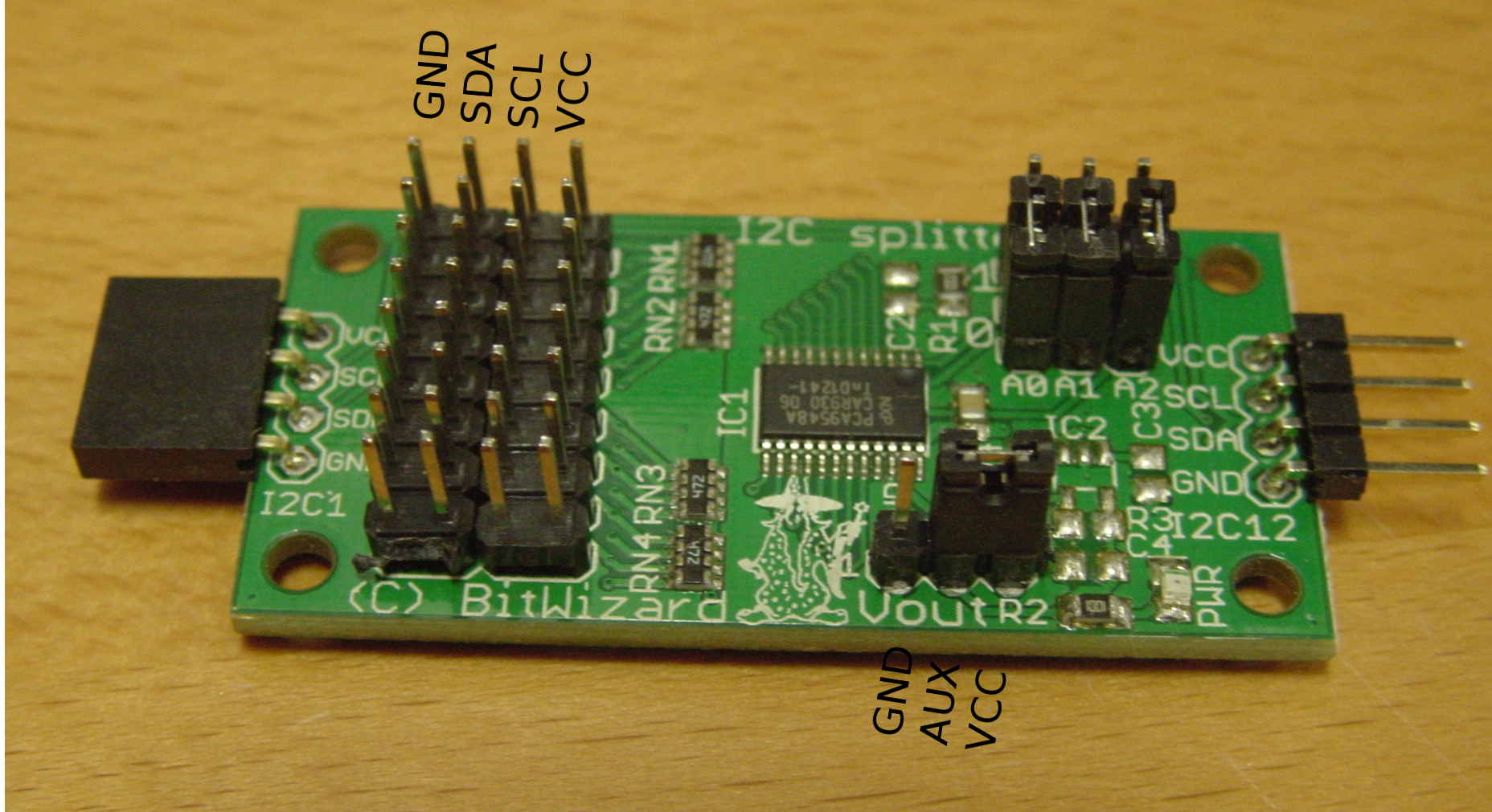
| 14:44, 3 June 2015 | Dsc05850 edit.jpg (file) |  |
817 KB | Rew | i2c_splitter with some pins labeled. | 1 |
| 11:43, 2 September 2015 | Dsc05937 small.jpg (file) |  |
182 KB | Rew | FPC connector as delivered. | 1 |
| 11:43, 2 September 2015 | Dsc05938 small.jpg (file) |  |
166 KB | Rew | 1 | |
| 11:44, 2 September 2015 | Dsc05939 small.jpg (file) |  |
150 KB | Rew | FPC connector with FPC inserted. | 1 |