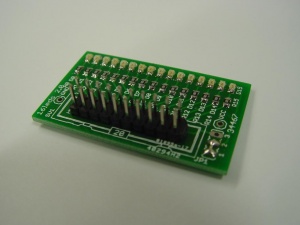
16 LEDs
This is the documentation page for the 16-LEDs board. That you can buy in the BitWizard shop.
Overview
A very useful board to test your digital outputs. Works on 5V as well as 3.3V so for the DIO as well as the Pi GPIO pins.
Must have! Use the 10x1Pin F-F kabel to hook it up to the boards (e.g. i2c_dio or spi_dio). Or if your board has a 10x2 pin header, you can use a 20pin IDC cable.
Assembly instructions
No user adjustable settings.
Possible Configurations
The 16-leds board can be ordered in two versions. The common-anode version will connect all the anodes to VCC (pin 19,20) and the leds via a resistor to the 16 inputs (pin 3-18). This means that the led will light up if you drive the input pin (3-19) LOW. This is useful for open collector outputs. However usually this results in inverted logic: the led lights when the signal is low.
Most people will want the common-cathode version. This connects all the cathodes to GND (pin 1/2) and then all the inputs to the leds. This results in normal logic: the leds light up if the signal is high.
Testing
To test the 16LED, connect the GND (pin 1 or 2) to any of the GND pins on your board.
Next take a 5V (or 3.3V) wire (pin 2 on DIO) and connect it one at a time to pin 3, 4, and so on. You can use a power supply pin or a pin programmed to "high". Each time you touch one of the inputs, one of the leds should light up.
External resources
Related projects
Pinout
| pin | function | ||
|---|---|---|---|
| 1 | 2 | GND | GND |
| 3 | 4 | LED0 | LED1 |
| 5 | 6 | LED2 | LED3 |
| 7 | 8 | LED4 | LED5 |
| 9 | 10 | LED6 | LED7 |
| 11 | 12 | LED8 | LED9 |
| 13 | 14 | LED10 | LED11 |
| 15 | 16 | LED12 | LED13 |
| 17 | 18 | LED14 | LED15 |
| 19 | 20 | VCC | VCC |
Jumper settings
Common Ground/Common VCC is hard wired in JP1.
| 1=2 3 | Common GND / kathode |
| 1 2=3 | Common VCC / anode |
Future hardware enhancements
The jumper is not much use: If you have the common cathode version the jumper must connect the common rail to GND, and if you have the common anode version, you must connect it to VCC. Therefore it makes more sense to make this a solder-jumper. It makes sense to design the board to have the GND signal the default because most people will want the normal-logic version i.e. the common cathode.
Changelog
2.0
- Initial public release
