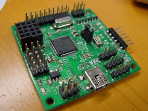
Stm32wifi
Overview
This board is meant to log sensor information over a WIFI link to a server with a database. It can also perform as an actuator, i.e. drive signals.
connectors
For sensors or actuators 5 three-pin connectors are provided. Each has the pinout GND, 5V, signal. Compatible sensors include DHT11, DHT22 and DS18B20. Compatible actuators are servos (software implementation TODO).
For sensors or actuators, a 6 pin SPI connector is available.
For configuration and debugging a 4-pin UART connection is available.
For sensors (and TODO: actuators?) two 4 pin I2C connectors are provided. Each has the pinout GND, SDA, SCL, 5V. Compatible sensors are currently MS5637 pressure sensors, but many other sensors are possible in future software updates.
For medium current applications, 4 open drain outputs are available. Max voltage: 20V. Max current: 1A/output. This is provided on a (2x3) 6-pin header. Pinout is GND, 5V, out0, out1, out2, out3.
For expansion IO a (2x10) 20 pin header is provided. Pinout is GND, GND, IO0, IO1, ... IO15, 5V, 5V.
jumpers
There is a three pin jumper J7. With 1-2 connected the board is in "normal operation" (Open often works as well, not recommended). With 2-3 connected the board is in bootloader mode. It will accept new firmware over USB in this mode. See Firmware upgrade STM32Wifi
There is a solder jumper that allows you to switch the 5V on most of the IO connectors to 3V3. Outputs will always be 3.3V levels, many inputs (but not all) are 5V tolerant. (TODO: check which ones).
leds
There is one power led near the SPI connector.
There are two programmable leds near the open drain output connector. Currently the software blinks one led regularly, and the other blinks the software-state. State 9 (nine blinks) is "normal operations".
Operation
Connect over the UART or (soon) over USB to the serial port of the board. Use 115200 baud. When the board boots you should see some information about the WIFI Module booting. When you hit enter you should get a prompt. Type "help" to see the list of commands and to double check that communication is working.
You can now enter the "wifi" command:
wifi <ssid> <wifipassword>
Put your own wifi credentials here, for example
wifi netgear4567 mypassword
Next issue the host command to enter the host and logging URL:
host <host> <logging url>
for example:
host www.bitwizard.nl /esp/logit.php?
Issue the uid command to get your module's unique id. You will need that to configure your device.
