Difference between revisions of "FT220X"
Jump to navigation
Jump to search
| (One intermediate revision by the same user not shown) | |||
| Line 1: | Line 1: | ||
[[File:FT220X.jpg|thumb|300px]] |
[[File:FT220X.jpg|thumb|300px]] |
||
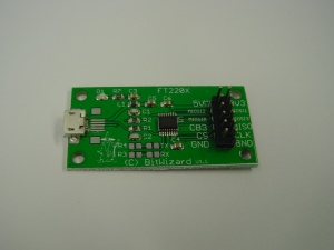
This is the documentation page for the FT220X breakout board. |
This is the documentation page for the FT220X breakout board. That can be bought in the [http://www.bitwizard.nl/shop/breakout-boards/ft220x-breakout-board BitWizard shop]. |
||
== |
== Overview == |
||
The FT220X breakout board has an USB connector, one 12-pin IO connector. The brains of the PCB, of course, is an FT220X chip. |
The FT220X breakout board has an USB connector, one 12-pin IO connector. The brains of the PCB, of course, is an FT220X chip. |
||
| Line 12: | Line 12: | ||
* [http://www.ftdichip.com/Products/ICs/FT220X.html FTDI product page] |
* [http://www.ftdichip.com/Products/ICs/FT220X.html FTDI product page] |
||
== |
== Pinout == |
||
The 12-pin connector is connected as follows: |
The 12-pin connector is connected as follows: |
||
| Line 34: | Line 34: | ||
No jumpers this time :) |
No jumpers this time :) |
||
== |
== Future hardware enhancements == |
||
Latest revision as of 16:48, 6 November 2015
This is the documentation page for the FT220X breakout board. That can be bought in the BitWizard shop.
Overview
The FT220X breakout board has an USB connector, one 12-pin IO connector. The brains of the PCB, of course, is an FT220X chip.
External resources
Pinout
The 12-pin connector is connected as follows:
| 5V | 3V3 |
| MIOSI2 | MIOSI3 |
| MIOSI0 | MIOSI1 |
| CBUS3 | MISO |
| CS# | CLK |
| GND | GND |
Please note: On version 1.1 of the boards, the silkscreen markings for MIOSI1 and MIOSI3 are switched!
LEDS
- The only LED is a power LED
Jumper settings
No jumpers this time :)
Future hardware enhancements
Changelog
1.1
- Initial public release
