Difference between revisions of "Dimmer"
| Line 28: | Line 28: | ||
When we want to trigger near the end of the half-wave, the current that starts flowing when the triac is triggered, may be below the so-called hold-current of the triac, so that the triac turns off immediately instead of conducting for a few ms (until the zero-cross) after triggering. On the other hand, we are timing the time to initiate the trigger based on the previous zero-crossing. If we measured a slightly larger value for the half-wave than what is currently happening, then we might even trigger the triac just AFTER the zero crossing. That would mean that the triac is on a whole half-wave instead of just a small part. You'll see flashes if this happens. Just use a slightly larger minimum value if this happens. |
When we want to trigger near the end of the half-wave, the current that starts flowing when the triac is triggered, may be below the so-called hold-current of the triac, so that the triac turns off immediately instead of conducting for a few ms (until the zero-cross) after triggering. On the other hand, we are timing the time to initiate the trigger based on the previous zero-crossing. If we measured a slightly larger value for the half-wave than what is currently happening, then we might even trigger the triac just AFTER the zero crossing. That would mean that the triac is on a whole half-wave instead of just a small part. You'll see flashes if this happens. Just use a slightly larger minimum value if this happens. |
||
=== protocol === |
|||
{|border=1 |
{|border=1 |
||
Revision as of 14:20, 6 April 2017
Overview
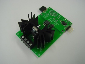
The dimmer can be used to control the intensity of lights. It works the same as regular dimmers that can be bought in any other hardware shop, but can be controlled over I2C. It should work with any I2C-capable device, including the Raspberry Pi, Arduino and many other microcontrollers.
The dimmer can be found here in the shop.
Control
The dimmer is at I2C address 0x9E. Port 0x10 is the intensity. The value written can be between 0 and 255, where 0 is the lowest intensity and 255 is the highest intensity. With bw_tool it can be controlled like this:
bw_tool -I -D /dev/i2c-1 -a 9e -W 10:xx:b
Where xx is the intensity in hex. (i.e. 00-ff, 80 is "half", 40 is "quarter" intensity).
Depending on your load, the first few values from 1-10 may not actually do something. Or they might do too much. In the past we adjusted for that, tweaking it for our test-load, but that tweaking didn't apply to other loads in the field, so we stopped doing that. The value you send is directly used by the hardware, but the lowest may result in even less output than commanded. So if you want your load to be on "low", a minimum value of "8" seems to be safe (and do very little).
Similarly, depending on your load and your mains waveform, setting values near 0xff will actually result in lower output than slightly lower values. Again this depends on lots of stuff and we can't tune it here so that the effect is totally hidden from you. Either limit yourself to a safe maximum like 0xf0, or test how far you can go and then take some margin. On my testsetup 0xfd was sometimes less bright than 0xfc. So around there is the limit so I could take some margin and use 0xf8 as the maximum value I will
When you write zero as the intensity, there will be no triggering of the triac at all, so "completely off".
technical stuff
If you don't care about the technical reasons for the above two paragraphs, skip to the next section.
The module uses a triac as the switching element. When you set the intensity to 50%, we simply trigger the triac at the top of the sinewave from the mains and the triac remains on until the next zero-crossing. Great. But at the ends different problems crop up.
When we want to trigger near the end of the half-wave, the current that starts flowing when the triac is triggered, may be below the so-called hold-current of the triac, so that the triac turns off immediately instead of conducting for a few ms (until the zero-cross) after triggering. On the other hand, we are timing the time to initiate the trigger based on the previous zero-crossing. If we measured a slightly larger value for the half-wave than what is currently happening, then we might even trigger the triac just AFTER the zero crossing. That would mean that the triac is on a whole half-wave instead of just a small part. You'll see flashes if this happens. Just use a slightly larger minimum value if this happens.
protocol
| address | datasize | description |
|---|---|---|
| 0x10 | byte | set/read intensity. 0 off. 0x08-0xf0 from low to high intensity. values outside this range at your own risk. |
| 0x14 | short | delta. When in a fade, use this step every 10ms. Signed 16 bit number. |
| 0x15 | short | fade length (remaining). Set this to non-zero to start a fade. Reads zero when the current fade is finished. |
So far all registers are read/write. (starting version 1.2). Before 1.2 only register 10 was implemented and it could not be read back.
