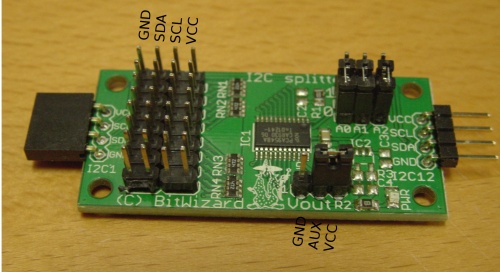
I2C splitter
general info
Based on the PCA9548A chip from NXP
http://www.nxp.com/documents/data_sheet/PCA9548A.pdf
I2C address:
1110 000 tru 1110 111 (jumper selectable)
Each I2C output has 4K7 pull-up resistors.
The address would be written "0x70" for the Linux I2C-tools. BitWizard "naming convention" would call this address "0xe0".
physical dimensions
- Board outline: 50x25mm
- Mounting hole diameter: 3mm
- Mounting hole pitch: 44x19mm (3mm from board edge)
pinouts
Hold the board such that the 4x8 pin array is on the left.
The 4x8 array has from left to right, GND (labeled "V-" because "GND" didn't fit), SDA (labeled DA), SCL (CL), and VCC (V+).
From top to bottom you will find bus 0 at the top to bus 7 at the bottom.
Connect your "master device" to the connector on the left or right. The pinout is GND, SDA, SCL, VCC from bottom to top.
The "Vout" connector provides GND/AUX/VCC. By placing a jumper on AUX/VCC, you can configure your slave I2C busses to use the same power supply as your main VCC (usually 5V or 3.3V). If you require a different voltage, you can apply that voltage using a two-pin connector using GND/AUX on the same connector. If you ordered the special version prepared for a specific output voltage, no connection/jumper is necessary on the VOUT connector. You can measure the output voltage on the AUX pin if you want (there are 8 other pins that make this voltage available, but it's there. :-) )
jumpers
address jumpers
It is recommended you use address 0 for the PCA9548A, unless that clashes with something on your I2C bus. Put all three jumpers to the position nearest you, in the position marked "0".
Power jumper/power connector
If your board has a jumper labeled "VOUT" near the bottom, this can be used to select the voltage level on the output bus. Connect a jumper on the rightmost two pins (AUX/VCC) to use the power from the "master" connector on the left or right of the PCB. If that is undesired, for example if your slave devices are 3.3V, you can connect a 3.3V power source to the ground pin on the left and the VAUX pin in the middle.
using the board
On the raspberry pi, the board can be controlled with i2cset:
i2cset -y 0 0x70 0x01
to for example select the first bus.
